
A transparent coating can make a glass surface reflect less light by creating an additional reflection. That sounds like a poor strategy: if the problem is unwanted reflections, why introduce another boundary that reflects light? Yet this is precisely the idea behind one of the most useful optical engineering tricks, the quarter-wave anti-reflection coating.
The extra reflection is not an added loss. When its phase and amplitude are chosen correctly, it cancels the original reflected wave. The energy that would have been reflected instead continues into the glass, assuming a transparent, non-scattering film. It is a practical demonstration that waves do not add like ordinary amounts of material: their electric fields add first, and intensity is determined afterwards.
Explore: why polished glass still behaves like a weak mirror
Imagine a laser beam entering a precision glass window. The glass is perfectly clean and smooth, yet a portion of the beam comes back toward the laser. That return light can create stray images, reduce signal, or disturb a sensitive optical cavity. The loss is not necessarily caused by a defect. It follows from Maxwell’s equations at a boundary between materials with different refractive indices.
At normal incidence, for a wave travelling from a medium of refractive index n0 to one with index ns, the electric-field reflection coefficient is
r = (n₀ − nₛ) / (n₀ + nₛ), and the reflected fraction of power is R = |r|².
For air (n0 ≈ 1.00) and a representative crown glass (ns ≈ 1.52), the result is R ≈ 4.26% at one surface. The light is not absorbed; it is sent in the wrong direction. An optical instrument with many interfaces can accumulate significant losses and unwanted secondary reflections. This is why a lens may look more transparent after receiving an apparently invisible film. The practical problem and its optical consequences are described in Edmund Optics’ technical guide to anti-reflection coatings.
Understand: engineer a second wave to undo the first
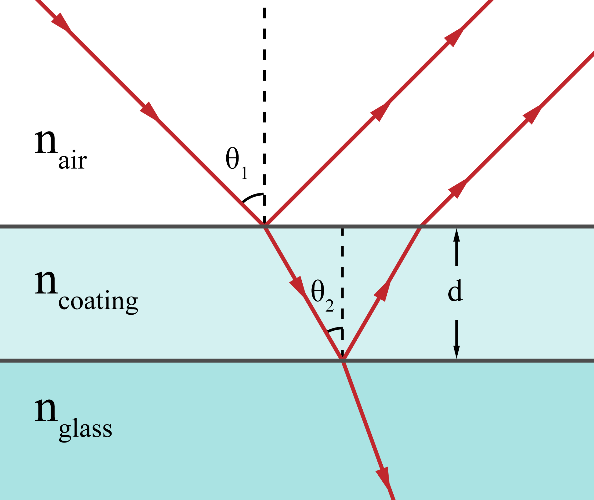
Place a thin, transparent film between the air and the glass. There are now two interfaces. Part of the incoming light reflects at the air–film surface (reflection A). Another part travels through the film, reflects at the film–glass surface, and returns through the film (reflection B). The two returning electric fields overlap in the air.
The trick requires two independent conditions: opposite phase and equal amplitude. If only the phases oppose, a larger wave leaves a residual reflection. If only the amplitudes match, the waves may reinforce rather than cancel.

Condition 1: make the return trip add half a wavelength
At the design vacuum wavelength λ0, choose a film thickness d such that its optical thickness is one quarter of a wavelength:
n_f d = λ₀ / 4, or equivalently d = λ₀ / (4 n_f), where nf is the film’s refractive index.
Reflection B travels down through the film and back up, so its extra optical path is 2 n_f d = λ₀ / 2. That introduces a phase difference of π radians, or 180°, between the two reflected contributions. In the usual air–film–glass ordering, both individual reflections also undergo the same reflection phase reversal, so their relative phase is governed by this extra path.
Notice the subtlety: the coating is not one quarter of a vacuum wavelength thick. Light has a shorter wavelength inside the film. A quarter-wave coating at 550 nm is therefore typically much thinner than 137.5 nm.
Condition 2: match the strengths of the two reflections
For non-absorbing materials at normal incidence, the amplitude reflection coefficients at the two boundaries are
r₀f = (n₀ − n_f) / (n₀ + n_f) and r_fs = (n_f − nₛ) / (n_f + nₛ).
At the quarter-wave thickness, the contributions cancel exactly when r₀f = r_fs. Solving that equality gives a remarkably simple design rule:
n_f = √(n₀ nₛ).
The film index should be the geometric mean of the indices on either side. This is the optical equivalent of matching an impedance in radio-frequency engineering: an intermediate layer can make an abrupt transition behave, at one frequency, as though there were no mismatch. The single-layer condition and its limitations are also explained by RP Photonics.
More exactly, multiple reflections bounce within the film. If δ = 2π n_f d / λ₀, the complete normal-incidence amplitude coefficient is
r_total = (r₀f + r_fs exp(2iδ)) / (1 + r₀f r_fs exp(2iδ)).
At a quarter wave, exp(2iδ) = −1; the numerator vanishes when the two interface coefficients are equal. The simple two-reflection picture captures the mechanism, while this expression accounts for all the smaller repeated reflections. It assumes flat, homogeneous, non-absorbing layers and coherent illumination.
A 100-nanometre example—and an unavoidable compromise
Take a green design wavelength of 550 nm and glass with ns = 1.52. The ideal film index in air is √1.52 ≈ 1.233. Its ideal physical thickness would be about 111.5 nm. Unfortunately, a robust, transparent solid film with that very low index is not generally available for ordinary glass optics.
A common practical material is magnesium fluoride (MgF₂), whose index is approximately 1.38 in the visible. For this material the quarter-wave thickness is 550 / (4 × 1.38) ≈ 99.6 nm. The phase condition is satisfied, but the amplitudes are not quite equal.
| Surface, at 550 nm | Approximate reflected power |
|---|---|
| Uncoated air–glass interface, n = 1.52 | 4.26% |
| Single quarter-wave MgF₂ film on that glass | 1.26% |
| Hypothetical ideal film, n ≈ 1.233 | 0% in the ideal model |
These are modelled values, not a guarantee for a particular commercial lens. They use fixed refractive indices, normal incidence, a perfectly uniform film and negligible absorption or scatter. Still, the scale is instructive: a layer only about one ten-thousandth of a millimetre thick removes roughly 70% of the original single-surface reflected power.
For a simple window with two independently treated surfaces, neglecting internal multiple reflections, the direct transmitted fraction rises from about (1 − 0.0426)² ≈ 91.7% to (1 − 0.0126)² ≈ 97.5%. That can matter in a chain of sensors, filters or lenses, where every lost photon reduces the available signal.
Where the beautiful solution breaks
Wavelength: the phase difference depends on λ. A layer tuned for green light is not perfectly tuned for blue or red. One quarter wave at the design wavelength is not one quarter wave everywhere. The index of the materials also changes with wavelength, adding dispersion.
Angle and polarization: oblique rays travel a different effective optical path through the film. The reflection coefficients for the two linear polarizations differ. A coating optimized for a laser entering straight on may perform differently for a wide-angle camera lens.
Manufacturing: thickness errors, roughness, contamination, stress, porosity and coating absorption all spoil the ideal cancellation. High-power laser optics must also survive intense fields without damage. Thin-film deposition is therefore as much a materials and process-control problem as an exercise in wave algebra.
Available materials: the geometric-mean index may be physically awkward to realize. Engineers then combine several layers with different refractive indices, or use gradually varying effective-index surfaces. Multilayer coatings can trade a perfect narrow-band minimum for good suppression over a broader spectral range. A technical introduction to optical coatings shows how film thickness and material choices are balanced in real products. Researchers have also explored subwavelength metamaterial structures as effective impedance-matching layers; see the open-access 2018 metamaterial anti-reflection study. Those structures should not be confused with a universally superior replacement for conventional coatings.
Shape: a small experiment in engineering with phase
There is a useful computational experiment that needs no optics laboratory. Set n₀ = 1, nₛ = 1.52, n_f = 1.38 and d = 99.6 nm. Evaluate the exact complex reflection formula above from 400 to 800 nm and plot |r_total|². Then repeat for 90 nm and 110 nm thicknesses. Where does the reflectance minimum move? How sensitive is the best wavelength to a ten-nanometre deposition error? Finally, replace n_f by √1.52 and compare the depth of the minimum.
The same mathematics suggests a broader engineering question: when is it better to eliminate a disturbance, and when can a carefully controlled second disturbance cancel it? Optical coatings exploit destructive interference in space; noise-cancelling headphones use related superposition ideas in acoustics, though with a very different feedback and control problem. Chirped-pulse amplification provides another example of controlling optical phase rather than merely controlling intensity.
There is a final inversion worth remembering. Rearrange thin-film layers so that reflected waves reinforce one another, and the same underlying physics builds an exceptionally good dielectric mirror. A transparent coating can either hide a surface or make it shine. The difference is how the phases are arranged.
Sources and further exploration
- RP Photonics, “Anti-reflection Coatings.” Technical reference for the single-layer geometric-mean rule, practical MgF₂ coatings, angular and bandwidth limits.
- Edmund Optics, “Anti-Reflection (AR) Coatings.” Optical-industry engineering guide to Fresnel loss, quarter-wave films and practical coating types.
- Justin Peatross and Michael Ware, Physics of Light and Optics, Brigham Young University. Open university optics textbook covering interference and Fresnel coefficients.
- R. M. A. Azzam (1985), “Single-layer antireflection coatings on absorbing substrates for the parallel and perpendicular polarizations at oblique incidence,” Applied Optics. Primary research illustrating how the simple design generalizes and becomes more complicated.
- F. Sepehripour, P. Karimi and A. Khavasi (2018), “Wideband Antireflection Coating Using Metamaterials.” Open research on engineered effective impedance and bandwidth.
For more mechanisms worth testing, see the Science & Engineering collection or share a question or experiment with Alkemata.
Author
What concrete example would confirm or challenge this article?
Choose a reaction, write a comment, or ask your AI assistant to send a proposal for review. Comments are reviewed before publication.