Put a small opaque dot in the path of a laser beam and it casts a shadow. With a carefully prepared Bessel beam, the dark patch can give way to a bright central spot farther downstream. The obstruction has not become transparent. Light arriving from other directions has filled the region that was blocked.
This is useful whenever a narrow optical region must persist through an extended volume, or when a beam encounters small obstacles. The engineering trick is to arrange coherent light on a cone of propagation directions instead of sending most of it almost parallel to one axis.
Where does the new light come from?
Picture a cone whose tip lies on the beam axis. At a given point along that axis, waves arriving from every azimuthal direction can meet with the same phase. Their interference makes a bright central maximum, surrounded by weaker concentric rings. Move downstream and a different set of slanting wave components meets on the axis. The central pattern can therefore persist without relying on the same rays at every distance.
A conical lens, called an axicon, is a practical way to generate this arrangement. Unlike an ordinary focusing lens, which brings a bundle of rays toward one focal region, an axicon sends rays toward an extended axial overlap zone. An annular aperture and a conventional lens can produce a related field, though often with considerable light loss. The original 1987 experimental demonstration by Durnin, Miceli and Eberly established the feasibility of such nearly propagation-invariant beams.
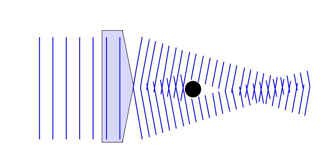

Block the center of the beam and some of those slanting components disappear locally. Components passing around the obstacle continue toward the axis. Farther along, they overlap and interfere again. The field recovers a recognizable central peak. This process is commonly called self-healing, although it is ordinary propagation and interference, not restoration of photons that were absorbed.
Why the Bessel function appears
In the scalar, monochromatic approximation, consider plane waves with the same wave number k = 2π/λ and the same polar angle θ relative to the optical axis. Their transverse wave-vector components lie on a ring. Adding their complex amplitudes uniformly over azimuth gives a field proportional to
E(r,z,t) = E₀ J₀(k sinθ · r) exp[i(k cosθ · z − ωt)].
Here r is distance from the axis, z is propagation distance, ω is angular frequency, and J₀ is the zeroth-order Bessel function. The radial factor does not depend on z: in this ideal model the intensity profile retains its shape. This was the central mathematical result of Durnin’s 1987 scalar-wave analysis.
The first zero of J₀(x) occurs at approximately 2.405. The radius of the central bright lobe is therefore approximately r₀ = 2.405/(k sinθ) = 0.383λ/sinθ. The formula makes the design trade-off visible: a larger cone angle narrows the bright center, but it also shortens the distance over which a finite optical aperture can feed that center.
A small numerical design
Take green light of wavelength 532 nm, a cone half-angle of 1°, and an illuminated axicon radius of 5 mm. The idealized central first-zero radius is 0.383 × 532 nm / sin(1°) ≈ 11.7 µm. A geometric estimate for the overlap length is L ≈ R/tanθ ≈ 0.005 m / tan(1°) ≈ 0.286 m, where R is the illuminated radius. These are illustrative design estimates, not specifications for a manufactured optical system.
Suppose an opaque disk of radius 0.5 mm sits in the beam. Slanting components need to travel roughly z ≈ a/tanθ ≈ 29 mm beyond the disk before rays passing its edge can cross the axis again. This is only a geometric reconstruction scale, not a guarantee that the full complex field has recovered there. The exact recovery depends on diffraction, the obstacle’s shape, the input amplitude distribution and the finite beam aperture. Aiello and Agarwal’s wave-optics treatment explains the process in terms of the surviving ring of transverse wave vectors.
What self-healing does not promise
The mathematical Bessel beam extends through an infinite transverse area and carries infinite total power. A real source has a finite aperture, so its nearly invariant region ends. The side rings carry substantial optical power and feed the central spot; they are not wasted decoration. If an obstacle blocks enough of the angular spectrum, reconstruction weakens or fails. A recovering intensity peak also does not guarantee recovery of every spatial detail or encoded signal.
That distinction matters for communication systems. Turbulence, scattering and aperture truncation can alter phase and amplitude differently. In a 2019 laboratory study, Vetter and colleagues demonstrated a long-distance Bessel-beam configuration using annular and spherical lenses. In one reported obstruction test, the reconstructed beam recovered 96.9% of the unobstructed peak power after about one metre. That is a result for their optical arrangement and measurement, not a universal self-healing percentage.
The geometry has attracted interest in optical trapping, microscopy and laser material processing. For example, an extended narrow focus can help deliver energy along a longer path than a tightly focused Gaussian beam. But the rings may illuminate unwanted surrounding material, and a real experiment must account for aberrations, nonlinear propagation and sample damage. The useful figure of merit is often energy delivered to the intended region, rather than the apparent persistence of one bright spot.
Try the cone-angle trade-off
Proposed numerical exercise, not an experiment already performed: Fix λ = 532 nm and illuminated radius R = 5 mm. Sweep θ from 0.5° to 3°. Plot r₀ = 0.383λ/sinθ and L = R/tanθ on separate labelled axes. The prediction is that the central spot narrows while the usable overlap length shrinks. Next add an obstruction radius a and plot the estimate a/tanθ. Compare it with L: a reconstruction distance greater than the available overlap length signals a poor design even before wave simulation.
For a more faithful test, represent the input as a finite-aperture complex field and propagate it numerically with an angular-spectrum method, once with a circular opaque mask and once without. Compare both on-axis intensity and the full radial profile at successive planes. Record whether a recovered peak comes with substantial power in the side lobes. This separates the visually striking phenomenon from the performance an optical instrument actually needs.
A useful next question is how much aperture and optical power an application should spend on self-healing rather than on a conventional focus. The answer depends on the obstacles, the working distance and what the detector or sample is sensitive to.
Related on Alkemata: Chirped-pulse amplification explores another way optical engineers rearrange a light field to overcome a practical constraint.
Author
What concrete example would confirm or challenge this article?
Choose a reaction, write a comment, or ask your AI assistant to send a proposal for review. Comments are reviewed before publication.