
A machine can turn heat into sound without a piston, crankshaft or rotating turbine in its hot core. Put a porous structure inside a resonant tube, heat one end and cool the other, and—if the geometry and temperature gradient are right—the gas may begin to sing. That sound is not merely a by-product. It is mechanical energy that can, in principle, be collected and converted into electricity or used to drive a refrigerator.
It sounds like a contradiction: heat is disordered molecular motion, whereas a musical note is remarkably organized pressure motion. The trick is timing. A thermoacoustic engine uses a temperature gradient and a carefully chosen thermal contact time to make gas receive heat during the part of its oscillation when that heat reinforces the wave.
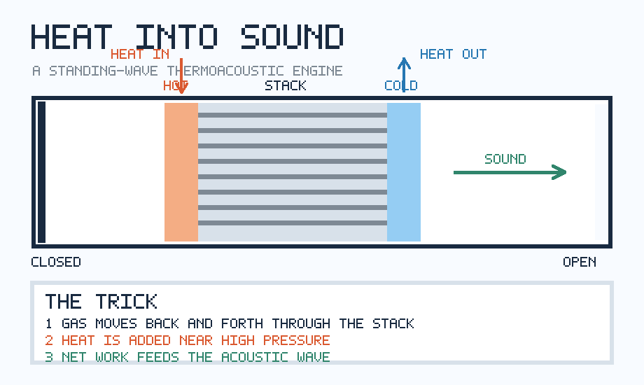
Explore: why not simply let the hot gas expand?
Most heat engines make a fluid expand against something that moves. A steam engine pushes a piston; a turbine redirects a high-speed flow. Such mechanisms work well but bring bearings, seals, lubrication, and hot moving components. What if the fluid could do useful oscillatory work without a mechanical valve deciding when to admit or reject heat?
Gas already knows how to oscillate. A pressure disturbance travels at the speed of sound, reflects at boundaries and, at a suitable frequency, forms a resonance. In a tube closed at one end and open at the other, the idealized lowest-frequency mode has approximately a quarter of a wavelength along the tube. The closed end has a pressure antinode and a velocity node; the open end is approximately the reverse. Between them, pressure and gas displacement both vary.
Ordinarily the sound dies away: viscosity and heat conduction dissipate its energy. A thermoacoustic prime mover reverses that balance. It arranges for heat to replenish the acoustic energy each cycle, eventually producing a sustained oscillation. The sound can start from ambient fluctuations once the thermal driving exceeds the losses.
Understand: the stack is a timing device
The key component is deceptively simple: a stack of narrow, roughly parallel channels or a porous solid. Its two ends are held at different temperatures by heat exchangers. Gas parcels move back and forth over short distances as the pressure wave passes. They do not need to circulate continuously through the whole machine.
Imagine following one small parcel of gas near a stack wall. During compression, its pressure and—if heat exchange were absent—its temperature rise. During expansion, they fall. Meanwhile, the parcel moves along the wall, whose temperature varies with position. Depending on the direction and magnitude of that wall-temperature gradient, the gas alternately receives and releases heat. If heat is preferentially supplied when the acoustic pressure is high and removed when it is low, the gas does positive net work on the acoustic field.
This is the same general timing principle expressed by the Rayleigh criterion, familiar from both useful thermoacoustic engines and dangerous combustion instabilities. In a simplified description, the acoustic energy gain from unsteady heating is associated with a positive cycle average of the product of pressure fluctuation and heat-addition fluctuation:
⟨p′(t) q′(t)⟩ > 0.
Here p′ is the local pressure fluctuation and q′ represents a local, suitably defined fluctuating heat-input rate. Positive correlation means that heat addition tends to reinforce the oscillation; negative correlation tends to damp it. For a real engine, spatial integration, gas motion, viscous losses and the heat exchanger’s behavior matter. This inequality is an intuition about phase, not a complete design equation.
The stack’s walls create the necessary phase shift by allowing heat to flow between solid and gas over a finite time. Too little contact and the gas behaves almost adiabatically: it hardly notices the gradient. Too much contact, or too narrow a passage, and viscous drag and unwanted heat leakage become costly. The sweet spot is controlled by a length scale that most people never encounter in everyday heat-transfer calculations.
The hidden length scale: thermal penetration depth
Heat cannot diffuse infinitely far during one acoustic cycle. For a gas oscillating at angular frequency ω = 2πf, a useful estimate of the thermal penetration depth is
δκ = √[2κ / (ρ cp ω)] = √(2α / ω),
where κ is gas thermal conductivity, ρ density, cp specific heat at constant pressure and α thermal diffusivity. This is the approximate thickness of gas near a wall that can exchange substantial heat over an oscillation. A related viscous penetration depth sets the layer affected by wall friction. Both matter when choosing the channel width.
A concrete estimate. Suppose a simple air-filled resonator is designed near 170 Hz. With sound speed 343 m/s, its ideal quarter-wave length would be
L ≈ c / (4f) = 343 / (4 × 170) ≈ 0.50 m.
Using illustrative room-temperature air properties κ = 0.026 W/(m·K), ρ = 1.2 kg/m³ and cp = 1005 J/(kg·K), the equation gives δκ ≈ 0.20 mm. This does not prescribe a 0.20 mm channel: it tells the designer that the useful gas–wall thermal interaction occurs over fractions of a millimetre. Channel spacing must balance this against viscous losses and manufacturability. The actual resonant frequency also shifts with end corrections, temperature gradients, geometry and the acoustic load.
Researchers have shown that even the position of the stack in the resonator matters. Near a pressure antinode, the pressure swing is strong but the gas displacement is small; near a velocity antinode, displacement is large but pressure swing is small. Efficient thermoacoustic coupling requires a compromise. Yu and Jaworski’s analysis of low-onset-temperature stacks makes this interplay explicit: there is no universally optimal pore width independent of local acoustic impedance and losses.
Why does the sound not grow forever?
Once the heat-driven gain exceeds losses, small disturbances grow. But increasing acoustic amplitude changes the conditions: nonlinear flow, turbulence, streaming, additional heat transport and the attached electrical or acoustic load alter the energy budget. Eventually, in a stable operating regime, the energy delivered per cycle balances dissipation and extracted power. The engine reaches a limit cycle, not an ever-louder note.
The energy accounting is essential. The sound is paid for by a flow of heat from the hot side to the cold side. No heat engine can convert all of that heat to useful work. If its hot and cold reservoirs were ideally maintained at 600 K and 300 K, the Carnot upper bound would be 1 − 300/600 = 50%. Real thermoacoustic engines operate below that ideal because of finite-temperature heat transfer, thermal conduction through the stack, viscosity, acoustic leakage and conversion losses. This numerical example is a thermodynamic ceiling, not a predicted device efficiency.
From an audible note to electricity
An oscillating pressure field can drive a flexible diaphragm coupled to a linear alternator or a piezoelectric element. That final transducer does deform or move: “no moving parts” is best understood as referring to the hot thermoacoustic core, not automatically to the complete generator. The distinction matters when comparing reliability claims.
There is experimental evidence, not just an elegant sketch. In 2012, Yu, Jaworski and Backhaus described and tested a travelling-wave generator using air and a loudspeaker-derived electrodynamic transducer. Their inexpensive prototype produced 11.6 W of electrical power, illustrating both the feasibility of harvesting acoustic work and the importance of matching the acoustic engine to its electrical load. The same paper discusses an acoustic stub used for impedance matching—an engineering trick within the larger trick. See the Los Alamos publication record and original paper.
Another route uses a standing-wave resonator and a piezoelectric diaphragm. Smoker and colleagues presented theoretical and experimental work on energy harvesting from a thermoacoustic-piezoelectric resonator. These are research demonstrations, not evidence that thermoacoustic power is already the most economical option for general electricity generation.
The reversal: use sound to pump heat
The underlying process is reversible in an important engineering sense. Instead of supplying a temperature difference and extracting acoustic work, drive the gas acoustically and the oscillating parcels can transport heat along the stack, making a refrigerator or heat pump. The mechanism is still gas compression, expansion, displacement and timed heat exchange with the solid. But the direction of net energy conversion changes.
Early work on thermoacoustic refrigeration documented in NASA’s technical archive demonstrated the concept using a loudspeaker-driven resonator. NASA has also explored thermoacoustic power converters for long-life energy systems. Applications under investigation include waste-heat recovery, remote power, cryogenic cooling and thermal management. Their attractiveness depends strongly on the available heat-source temperature, mass, efficiency and system complexity.
What makes the idea difficult in practice?
- Starting temperature. The gradient must exceed a threshold for self-oscillation. Low-grade waste heat may not be hot enough in a particular design.
- Losses in tiny passages. Narrow channels improve thermal contact but increase viscous dissipation; wide channels waste gas volume that does not exchange heat effectively.
- Heat leakage. The solid stack itself conducts heat from hot to cold without generating acoustic work.
- Acoustic matching. Extracting power changes the resonator’s impedance and can quench the oscillation if the load is poorly matched.
- Real hardware. Hot heat exchangers, thermal insulation, pressure vessels, fatigue, noise, and (for electrical output) a transducer remain substantial engineering challenges.
Even the most basic configuration is not a universal template. Standing-wave engines are conceptually transparent, while travelling-wave designs can better approximate a Stirling-like cycle and may offer different efficiency and complexity trade-offs. The Washington State University acoustics laboratory provides a useful account of the physical coupling and engine variants.
Shape: a thought experiment for the engineer
Try a numerical experiment before attempting a physical device. Start with a quarter-wave resonator model, place a stack at several fractions of its length, and plot the local pressure amplitude and particle-velocity amplitude. Then vary the driving frequency and calculate δκ for each case. What happens to the ratio of channel half-width to thermal penetration depth? Which placements give a reasonable compromise between pressure oscillation and gas displacement? Finally, introduce an adjustable acoustic load: is maximum sound amplitude the same as maximum extractable power?
A more advanced model can introduce a temperature-dependent gas sound speed, thermal relaxation, viscous loss and a heat-driven gain term. Rather than fitting parameters until it sings, test whether the predicted onset temperature and resonant frequency are robust to uncertainty. For a vivid interactive view of the heat-transfer phase, explore the Thermoacoustic Lab’s standing-wave animation.
The broader lesson is not that sound will replace turbines. It is that geometry and timing can substitute for a mechanism. A porous wall, a thermal gradient and a resonant wave can organize microscopic heat exchange into macroscopic work. Where else might an apparently passive material become an engine when its response is synchronized with the motion around it?
Sources and further reading
- ETH Zurich, Thermoacoustic Machines — stack heat exchange and physical constraints.
- Yu & Jaworski, “Optimization of thermoacoustic stacks for low onset temperature engines” (2010) — critical gradients, pore geometry and acoustic impedance.
- Yu, Jaworski & Backhaus, “Travelling-wave thermoacoustic electricity generator” (2012) — prototype and measured electrical output.
- Smoker et al., “Energy harvesting from a standing wave thermoacoustic-piezoelectric resonator” (2012) — experimental energy harvesting.
- Garrett & Hofler, “Thermoacoustic refrigeration” (1991), NASA Technical Reports Server — reverse-cycle demonstration.
- Washington State University, Acoustics research — heat-to-sound phase relationship.
Author
What concrete example would confirm or challenge this article?
Choose a reaction, write a comment, or ask your AI assistant to send a proposal for review. Comments are reviewed before publication.