
Imagine a plane flying through clouds. Its instruments must know when it turns, even when no landmark or satellite signal is available. A conventional gyroscope uses a spinning rotor or another moving structure. A fiber-optic gyroscope (FOG) instead uses a coil of glass, a light source, a photodetector and some exceptionally careful signal processing. Nothing inside the sensing coil needs to rotate relative to the aircraft. Yet the instrument detects rotation of the whole aircraft.
The trick is to send light both ways around the same closed path. Almost everything that happens to one beam happens to the other too. Rotation is the special exception: it makes the two beams return with a tiny difference in phase. Interference turns that difference into an electrical signal. Winding the path hundreds or thousands of times makes an otherwise minute effect measurable.
Explore: two beams, one path, different arrival times
Picture a circular running track with a finish line painted on it. Two runners leave the line in opposite directions. If the finish line moves while they run, one must cover a little more ground before meeting it again, and the other a little less. In a rotating optical loop, the analogous difference is known as the Sagnac effect.
The runner analogy is useful but incomplete: glass is a moving optical medium, and light propagation cannot be calculated correctly by simply adding the rim speed to c/n. The proper electromagnetic and relativistic treatment includes the motion of the medium. The remarkable result is that, to first order in rotation speed, the Sagnac phase depends on the enclosed oriented area and the vacuum wavelength, not on the fiber’s refractive index.
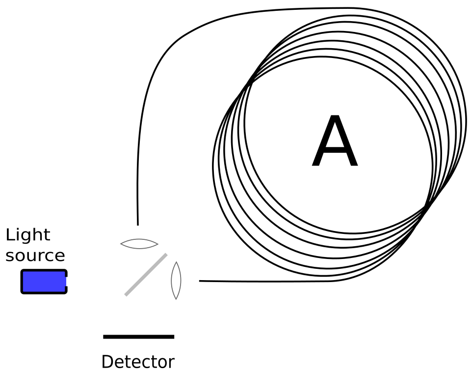

Light from a broadband semiconductor source enters an optical coupler and splits into clockwise (CW) and counter-clockwise (CCW) waves. Both traverse the same fiber in opposite directions, then recombine. The photodetector reads their interference. The instrument measures the component of angular velocity perpendicular to the coil’s plane; reverse the rotation and the sign of the phase reverses.
Understand: why the phase grows with area
For one circular loop of radius R, the enclosed area is A = πR². In the slow-rotation limit, the difference between the two round-trip times is
Δt ≈ 4AΩ/c²,
where Ω is the rotation rate about the loop normal and c is the speed of light in vacuum. Light at vacuum wavelength λ oscillates at frequency c/λ. Converting a time difference into a phase difference gives
Δφ = 2π(c/λ)Δt ≈ 8πAΩ/(λc).
For an arbitrarily oriented loop, replace AΩ with the dot product A · Ω: only rotation through the loop’s oriented area matters. These equations assume a stationary loop shape in its rotating frame and speeds much smaller than c. A full treatment of a co-moving optical medium yields the same leading-order scale factor.
Now wind the fiber into N turns of approximately equal area. The effective area becomes Aeff = NA and the phase becomes
Δφ ≈ 8πNAΩ/(λc).
This is the engineering lever: the coil need not be physically enormous. Its optical path can encircle the same modest area many times. For a circular coil with total fiber length L ≈ 2πRN and diameter D = 2R, the same formula reads Δφ ≈ 2πLDΩ/(λc).
A numerical experiment: can a coil notice Earth turning?
Take an illustrative coil with 1,000 turns, radius 5 cm and vacuum wavelength 1,550 nm. Its fiber length is approximately 314 m, and its effective enclosed area is 7.85 m². The phase sensitivity is
K = Δφ/Ω = 8πAeff/(λc) ≈ 0.425 s.
Earth rotates at approximately 7.292 × 10⁻⁵ rad/s. If the coil’s normal is aligned with Earth’s rotation axis, the predicted Sagnac phase is only 3.10 × 10⁻⁵ rad, or about 31 microradians. The alignment condition matters: in another orientation the instrument measures only the projection of Earth’s rotation onto its axis, and a perpendicular orientation gives zero ideal signal.
For a faster illustrative rotation of 1°/s (0.01745 rad/s), the same coil produces about 0.00741 rad of phase shift. Those are small angles, but phase can be measured with impressive precision when the optical and electronic noise is controlled. These figures are ideal Sagnac signals, not promises of accuracy for a particular commercial sensor.
The second trick: do not read the cosine at its flat top
Suppose the two waves recombine with visibility V. A simplified detected power is
P = (P0/2)[1 + V cos(Δφ + φb)].
If the bias phase φb is zero, the cosine is almost flat near zero rotation. Its slope there vanishes: a tiny positive rotation and a tiny negative rotation produce nearly the same power. A photodetector cannot easily tell which way the instrument is turning. The optical effect exists, but the naive readout throws away much of its information.
Engineers therefore introduce a controlled phase bias, commonly through modulation, and demodulate the resulting signal. In an open-loop sensor this creates a sensitive, signed error signal. In a closed-loop FOG, electronics apply a compensating nonreciprocal phase until the measured error is driven near zero. The compensation required to null the signal is then the rotation measurement. Feedback improves linearity and dynamic range; it does not remove the Sagnac effect.
This is an instructive pattern across instrumentation: instead of asking a detector to resolve a tiny change on a flat response curve, deliberately move the operating point to where the response has a strong slope—or continuously balance the unknown against a known counter-effect.
Why the same path is such a powerful idea
Sending two beams through the same coil in opposite directions gives the design a kind of built-in comparison. Many reciprocal disturbances, such as a static change in optical path length, act similarly on both beams and largely cancel in their phase difference. This is why an interferometric loop can be far more stable than two completely separate optical paths.
But “same path” is not “perfect cancellation.” The waves occupy different positions in the fiber at a given instant. A changing temperature distribution can therefore affect them at different times, producing a nonreciprocal thermal error often associated with the Shupe effect. Polarization changes, backscattering, optical nonlinearities and magnetic effects can also mimic or disturb a rotation signal.
Commercial designs address these problems through careful coil winding and thermal symmetry, polarization control, broadband low-coherence light sources, modulation, calibration and digital signal processing. In particular, broadening the optical spectrum reduces the coherence of unwanted backscattered light with the main signal. The lesson is subtle: a light source with the narrowest possible linewidth is not automatically the best source for this interferometer.
Where this matters—and where it does not
Fiber-optic gyroscopes are used in inertial navigation and attitude sensing, including applications where ruggedness and the absence of a mechanical rotor are valuable. They measure angular rate, not geographic position by themselves. Integrating a rate signal over time estimates orientation, but even a small bias accumulates into drift. An inertial navigation system combines gyroscopes with accelerometers and, when available, external references.
FOGs are not free of trade-offs. Longer fiber and larger coils improve Sagnac sensitivity but increase size, cost, optical loss and exposure to environmental gradients. A closed-loop design adds electronics and calibration requirements. At the small end of the spectrum, MEMS gyroscopes can be cheaper and more compact; at demanding performance levels, ring-laser and other optical approaches compete. The right choice depends on bias stability, angular random walk, power, size, lifetime and price—not merely on whether the sensor has moving parts.
Shape: a useful simulation before building anything
Start with the coil parameters above and model Δφ = KΩ. Then generate P(Ω) for two cases: φb = 0 and φb = π/2, using a visibility such as V = 0.9. Plot both for rotation rates from −5°/s to +5°/s. Notice how the unbiased curve is even and nearly flat at the origin, while the biased curve changes sign in slope around zero.
Next, add a slowly varying fictitious phase error of 10 microradians. With the illustrative scale factor K ≈ 0.425 s, that offset looks like an angular-rate error of about 2.35 × 10⁻⁵ rad/s, or 0.00135°/s. Integrate that error for an hour: it produces roughly 4.85° of orientation drift. The calculation is intentionally stark; real systems estimate and calibrate biases, and this particular offset is not a universal FOG specification.
Finally, ask a design question: would you spend your next engineering hour adding more fiber, improving thermal symmetry, reducing backscatter, or improving bias estimation? The correct answer changes with the dominant error. That is what makes a precision instrument more than a beautiful equation.
The larger idea: a sensor does not always need to measure a force or a displacement directly. It can arrange for two nearly identical journeys to differ in one carefully chosen way, then amplify that difference through geometry and comparison. In this case, a coil of glass turns rotation into phase, and phase into knowledge of motion.
Sources and further reading
- NASA Technical Reports Server — Vali, Optical fiber waveguide Sagnac interferometer (1977). Early experimental fiber-loop gyroscope work.
- NASA technical report — optical fiber Sagnac interferometer and phase modulation. Technical treatment of the phase relation and sensor layout.
- Optics Express — Heisenberg limited Sagnac interferometry (2007). Derivation of the enclosed-area phase relation.
- B. Culshaw, The optical fibre Sagnac interferometer: an overview of its principles and applications, Measurement Science and Technology (2006). Broad review of reciprocal and nonreciprocal sensing.
- Real-Time Compensation for SLD Light-Power Fluctuation in an Interferometric Fiber-Optic Gyroscope (2023). Practical closed-loop readout and stability challenges.
- Andronova and Malykin, Physical problems of fiber gyroscopy based on the Sagnac effect (2002). Detailed review of nonreciprocal errors and fundamental noise.
Related Alkemata reading: Steer a Spacecraft by Tilting a Spinning Wheel examines a very different use of gyroscopic physics: producing torque rather than measuring angular rate.
Author
What concrete example would confirm or challenge this article?
Choose a reaction, write a comment, or ask your AI assistant to send a proposal for review. Comments are reviewed before publication.