
Imagine a rotating shaft whose angle is read through five digital tracks. At the instant it crosses a boundary, several sensors may change state. The electronics cannot guarantee that all their signals arrive together. A seemingly harmless binary number can therefore briefly report an angle nowhere near the shaft’s actual position.
Engineers can arrange the codes around the circle so that only one bit changes at each boundary. This is Gray code, a small mathematical rearrangement with consequences for rotary encoders, analog-to-digital conversion and communication between independent digital clocks.
The dangerous boundary
A conventional four-bit binary counter goes from 7 to 8 by switching 0111 to 1000. All four bits change. If a receiver observes some wires before they switch and others afterward, it might briefly see 0000 or 1111, among other mixtures. Neither represents the actual neighbouring positions. The precise intermediate value depends on timing and circuit behaviour; these are illustrative possibilities, not measured traces.
For a four-bit reflected Gray sequence, the same numerical positions are represented by 0100 and 1100. Only the leading bit switches. A sample taken near the boundary is ideally either the old code or the new one. The price is that the transmitted pattern is no longer the familiar binary representation of the count.
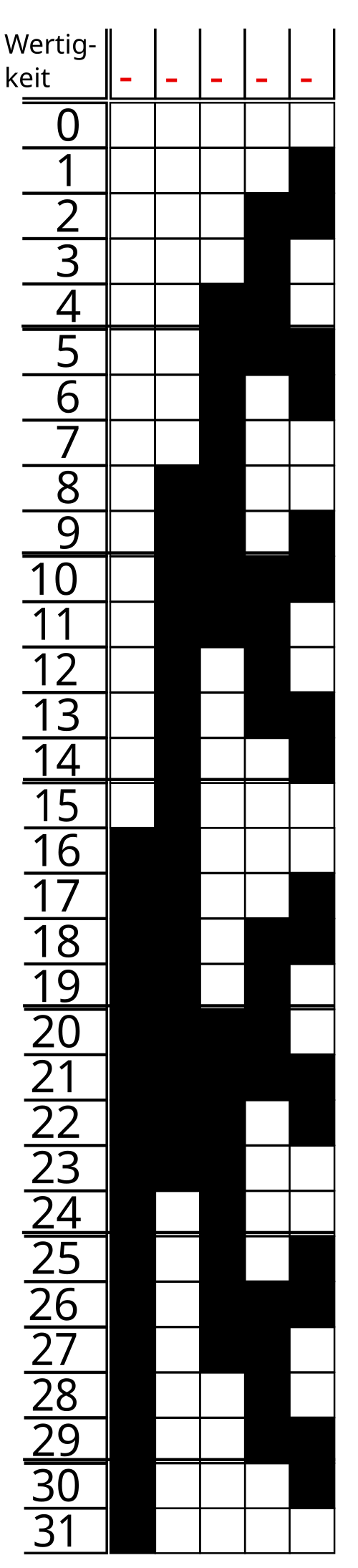

How to construct the sequence
Let b be a non-negative binary integer and let g denote its reflected Gray representation. The conversion is remarkably compact:
g = b XOR (b >> 1)
Here >> 1 shifts the bits right by one place, and XOR produces 1 wherever its inputs differ. For example, decimal 7 is 0111; shifting gives 0011, so XOR yields 0100. Decimal 8 is 1000; its shifted value is 0100, giving 1100.
Why does the trick work for every successive count? Incrementing a binary integer flips a run of trailing ones and the zero immediately before them. In the XOR-with-shift representation, adjacent flips cancel in pairs, leaving one changing Gray bit. This is a property of consecutive positions in the reflected sequence, including its wraparound for a fixed-width counter.
Conversion back is also simple: the highest binary bit equals the highest Gray bit; each lower binary bit is the XOR of the Gray bit at that position and the already recovered binary bit immediately above it. In software, the same operation can be implemented as a prefix XOR.
Where a physical sensor benefits
In an absolute optical rotary encoder, patterned rings pass in front of detectors. Each ring contributes one bit to the angular position. A five-track encoder provides 32 distinct codes, corresponding to 360°/32 = 11.25° per nominal sector. Near a sector boundary, finite detector widths and imperfect alignment make the exact switching instant uncertain.
If four tracks change together, a momentary mixed code can suggest a position many sectors away. With Gray patterns, the intended neighbouring sectors differ in one track, reducing the boundary ambiguity to one sector under the assumption that the sensor is near only one boundary and its individual tracks behave correctly. Gray coding does not cure a broken detector, dirty disk or arbitrary noise.
The same reasoning appears in high-speed flash analog-to-digital converters. Comparator decisions near thresholds may be delayed or metastable. Analog Devices’ MT-020 converter tutorial describes Gray decoding as one way to constrain the magnitude of errors associated with ambiguous decisions, rather than allowing a large incorrect binary code. The exact error bound depends on the converter architecture and encoding.
Two clocks, one buffer
A subtler use arises when one digital subsystem writes samples into memory while another reads them using an unrelated clock. A first-in-first-out (FIFO) buffer has separate write and read pointers. Each side needs to know approximately how far the other has progressed, to avoid reading an empty buffer or overwriting unread data.
Directly sampling a changing multi-bit binary pointer in the other clock domain risks combining bits from different counts. A common architecture keeps binary pointers locally for memory addressing, converts them to Gray code for transfer, and passes each Gray bit through synchronizing registers before comparing pointers. The technique is detailed in Clifford Cummings’ 2002 asynchronous-FIFO design paper.
There is an important qualification. Gray coding alone does not remove metastability. A flip-flop sampling a changing input can take an uncertain time to settle. Synchronizers reduce the probability that this unsettled state propagates. Moreover, the physical routing must limit relative delay between Gray bits: if consecutive transitions overlap at the destination, even a nominally one-bit-at-a-time sequence may be observed incorrectly. Proper clock-domain-crossing constraints and verification remain essential.
This also explains why a synchronized FIFO pointer may lag the true pointer. Full and empty flags are designed to be safe despite that delay, although the conservatism can temporarily reduce usable throughput. The extra circuitry and latency are the cost of crossing the clock boundary reliably.
A small experiment with a large error
Proposed simulation, not an experiment already performed. Generate consecutive four-bit counts, and model each wire’s switching delay independently. At the 7-to-8 boundary, assign delays of 0, 1, 2 and 3 nanoseconds to the four binary bits. Sample every 0.25 ns, decode each intermediate pattern and plot the apparent count. Repeat with the Gray representations 0100 and 1100, changing only the one required wire. The binary trace can report intermediate counts far from 7 and 8; the Gray trace should show only those adjacent values in this idealized model.
Then add a second Gray transition before the first has propagated fully. That deliberately violates the single-transition-in-flight assumption and reveals why a digital encoding rule cannot replace physical timing constraints. A useful extension is to repeat the test with a synchronizer model, recording latency and any remaining uncertainty.
Gray code illustrates a distinctive design choice: sometimes the best representation of a number is the one that makes transitions physically less ambiguous. For another example of timing as an engineering resource, see Alkemata’s Vernier delay-line timing article, which exploits small differences between propagation delays rather than trying to eliminate them.
Technical sources
Analog Devices, MT-020: ADC Architectures I: The Flash Converter; Analog Devices, Demystifying the Conversion Error Rate of High Speed ADCs; Cummings, Simulation and Synthesis Techniques for Asynchronous FIFO Design (2002).
Author
What concrete example would confirm or challenge this article?
Choose a reaction, write a comment, or ask your AI assistant to send a proposal for review. Comments are reviewed before publication.