
Imagine a satellite that has exhausted its propellant but still needs to leave a crowded orbit. It could unfold a conductive ribbon hundreds of metres long. No rocket plume appears. No tank is emptied. Yet the satellite can gradually lose orbital energy and descend. The ribbon is not a parachute: it is a generator whose electrical current feels a force from Earth’s magnetic field.
This is the electrodynamic tether, a particularly elegant combination of Faraday induction, plasma physics and orbital mechanics. Its most surprising feature is that the same electrical interaction can either remove energy from an orbit or, with external electrical power, help raise it. The crucial difference is which way energy flows.
Explore: why a wire can be more useful than a fuel tank
Spacecraft in low Earth orbit move at roughly 7–8 kilometres per second. Although the atmosphere is tenuous, the region is crowded with active satellites, spent upper stages and debris. End-of-life disposal matters: a satellite that remains in orbit can pose a collision risk long after it stops working. A propulsion system can lower its orbit, but propellant must be carried from launch and the disposal hardware must still operate after years in space.
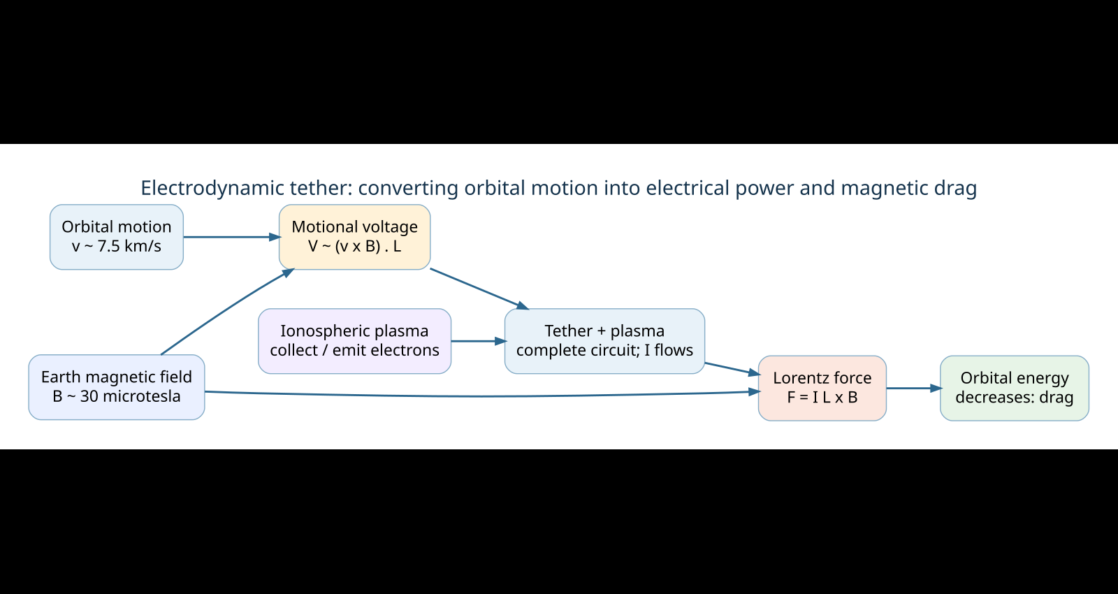
A conductive tether offers a different exchange. Instead of expelling reaction mass, it interacts with the geomagnetic field and the surrounding ionospheric plasma. The moving wire generates a voltage. If electrons can enter at one part of the tether and leave at another, current flows. The magnetic field then pushes on that current-carrying conductor. In the passive, generating configuration, the force has a component opposite the orbital motion.
It sounds suspiciously like free propulsion. It is not. The tether is a device for converting orbital mechanical energy into electrical energy and heat. For deorbiting, that is exactly what we want.
Understand: a moving conductor is a battery
Begin with the Lorentz force on an electric charge:
F = q (E + v × B).
Here q is the charge, E the electric field, v the velocity relative to the magnetic-field/plasma environment and B the magnetic field. Charges inside a conductor moving across magnetic field lines are driven sideways by q(v × B). They redistribute until an electric field balances that magnetic force, producing a potential difference along the conductor.
For a straight tether of vector length L, a useful idealized expression is:
V_motional = (v × B) · L.
The dot product matters: only the component of v × B along the tether contributes. The voltage is not simply speed multiplied by magnetic-field strength multiplied by length in every orientation.
Take an illustrative one-kilometre tether, a relative speed of 7,500 m/s and a magnetic field of 30 μT. In the favourable perpendicular geometry, the induced voltage magnitude is:
V ≈ (7,500 m/s)(30 × 10⁻⁶ T)(1,000 m) = 225 V.
That is a substantial voltage from a thin wire, without any onboard generator shaft. But 225 V is an open-circuit idealization, not a guarantee of 225 W of usable power. To draw current, the electrical circuit must actually close, and its resistance and plasma interfaces matter.
The missing return wire is the ionosphere
In a terrestrial circuit, we connect the two terminals of a battery with a return conductor. An orbital tether generally has no second long metallic wire. Instead, the tenuous ionospheric plasma supplies a distributed electrical return path. One end or bare positively biased section collects electrons; an electron emitter or plasma contactor can release electrons at the other end. The current path therefore includes the tether, its interfaces and the ambient plasma.
That is why a bare metal tape can be more effective than a perfectly insulated wire. A long, positively biased section collects electrons along its length, rather than relying on a small collector at the tip. Plasma sheaths, electron density, temperature, orbital motion and the electron emitter all influence the resulting current. A wire hanging in a vacuum with no effective current closure would develop a voltage but deliver little sustained magnetic drag.
The European Commission-funded BETS project investigated bare electrodynamic tethers and highlighted an unexpected engineering advantage of tape geometry: for comparable mass, a thin, wide tape can expose more collecting perimeter than a round wire, while its vulnerability to debris cuts can differ substantially. Shape matters as much as conductivity.
Why current makes the orbit change
A current-carrying conductor in a magnetic field experiences a force. In the simplest straight, uniform-field approximation:
F = I (L × B).
With I = 1 A, L = 1,000 m and B = 30 μT perpendicular to the wire, the force magnitude would be 0.030 N. That is only thirty millinewtons, approximately the weight of a few grams on Earth. But it can act for many orbits, and a satellite in free flight does not need a large continuous force to change its trajectory.
Now check the energy bookkeeping. If that force points opposite a 7,500 m/s orbital velocity, the mechanical power extracted is:
P_mechanical = F · v ≈ −(0.030 N)(7,500 m/s) = −225 W.
At the same time, our idealized tether produces V I = (225 V)(1 A) = 225 W of electrical power. The equality is not a coincidence. It is the electromagnetic version of conservation of energy: in a generator, the mechanical motion supplies the electrical power. Real systems divide that energy among useful loads, tether resistive heating, plasma losses and other processes. A realistic design cannot assume one ampere without modelling the complete plasma circuit.
There is also a subtle orbital-mechanics trap. A tangential braking force initially reduces velocity, but as the spacecraft moves to a lower circular orbit its circular orbital speed is actually higher. What the tether reliably removes is orbital mechanical energy, not necessarily the numerical speed you would measure after the orbit has circularized.
Where does the momentum go?
A tether is not a reactionless drive. The current interacts with Earth’s magnetic field and the ionospheric environment; momentum is exchanged with that larger electromagnetic system. A local magnetic force on the tether is balanced by reaction forces elsewhere in the coupled system. Calling the process “propellantless” means that the spacecraft does not need to throw away its own reaction mass, not that it violates Newton’s laws.
Reverse the direction of current using an onboard power source, such as solar arrays, and the Lorentz force can acquire a forward component, adding orbital energy. In this motor mode the spacecraft pays with electrical power instead of propellant. The available thrust direction and efficiency vary with orbital inclination, magnetic-field orientation and the plasma return path; the tether is not an all-direction thruster.
What has actually flown?
There is experimental evidence for the electromagnetic effect, but it is important to separate that from a fully operational disposal service. During the NASA–Italian Space Agency TSS-1R mission in February 1996, a nearly 20-kilometre tether generated voltages above 3,500 V and, in some operating/failure conditions, currents around or above 1 A. The tether broke during deployment after a high-voltage electrical failure. The mission nevertheless yielded valuable measurements of how orbital conductors exchange current with plasma. NASA’s technical account and the mission overview document the science and the failure.
The planned ProSEDS experiment was designed to use a five-kilometre bare conducting section plus ten kilometres of nonconducting tether to accelerate orbital decay and generate limited power. It was cancelled before flight, not a successful in-orbit demonstration; NASA’s mission development review explains the history.
More recently, the European E.T.PACK-F programme has pursued a shorter bare aluminium tape. In an April 2026 project update, the mission team described a 420-metre, 2.5-centimetre-wide tether and a planned in-orbit demonstration in 2027. That is a reported plan and hardware-development milestone, not yet flight-proven performance.
Engineering reality: the clever part is only half the system
Deployment and dynamics. A kilometre-scale conductor must be stored, released and kept sufficiently extended. Gravity-gradient effects can help orient it near the local vertical, but libration, tether elasticity, orbital perturbations and Lorentz torques complicate the motion. A deployed tether also creates a collision and entanglement hazard of its own.
Plasma variability. Electron density and temperature change with altitude, sunlight, geomagnetic activity and location. Current collection and emission can become the limiting factor, not the conductor’s resistance. Electron emitters may need power or consumables; concepts relying on passive emission have their own material and thermal constraints.
Electrical and material survival. High potentials invite arcing and insulation problems, as the TSS-1R failure illustrated. Micrometeoroids and orbital debris can sever a thin wire. Tapes, segmented designs and protection strategies reduce some risks but do not make them disappear.
Mission geometry and safety. A tether works best when its direction, motion and magnetic field have favourable relative orientations. Performance can vary around each orbit. Uncontrolled orbital lowering also requires collision-risk assessment, and a large spacecraft may still need a controlled final re-entry. The technology must be judged against drag sails, electric thrusters and conventional disposal systems for the actual mission.
Shape: an experiment you can run on a laptop
Start with a deliberately simple model: a 100 kg satellite in a circular low Earth orbit, a 1 km tether, B = 30 μT, and a hypothetical fixed current of 1 A. Assume the geometry stays perpendicular and the magnetic force points exactly backward. Calculate F = I L B, then the instantaneous orbital-energy extraction −Fv. Use E_orbit = −GMm/(2a) for a circular orbit to estimate the change in orbital semimajor axis from the power loss. Do not simply subtract a constant amount from orbital speed and call that the new circular orbit.
Then improve the model in stages: vary the field direction over an orbit; make current a function of induced voltage and an effective plasma-interface resistance; impose an eclipse-dependent power budget for active reboost; add a simple deployment mass and collision-risk penalty. You will discover that a force that looks trivial in a textbook becomes a genuine systems-engineering trade-off once the electrical return path and orbital geometry are included.
A further question is worth exploring: could a satellite carry a tether that normally acts as a generator, then use stored solar energy to reverse its current for occasional orbit correction? The answer depends less on whether Maxwell’s equations permit it—they do—than on whether deployment, plasma contact, controllability, reliability and mass make the whole spacecraft better.
For a contrasting way to control spacecraft motion, see Alkemata’s control-moment gyroscope explainer: a spinning wheel redistributes angular momentum inside a spacecraft, whereas an electrodynamic tether exchanges momentum with its environment.
Sources and further exploration
- European Commission, BETS final report: Propellantless deorbiting of space debris by bare electrodynamic tethers. Primary project report on current collection, tape design, mission dynamics and limits.
- N. H. Stone and W. J. Raitt, The TSS-1R Electrodynamic Tether Experiment: Scientific and Technological Results, NASA Technical Reports Server (1998).
- N. H. Stone and C. Bonifazi, The TSS-1R Mission: Overview and scientific context, Geophysical Research Letters 25 (1998). Peer-reviewed mission overview.
- J. A. Vaughn and colleagues, Review of the ProSEDS Electrodynamic Tether Mission Development, NASA/AIAA (2004). Explains why a planned mission did not fly.
- G. Sánchez-Arriaga and X. Chen, Modeling and Perspectives of Low-Work-Function Electrodynamic Tethers to Deorbit Space Debris, ESA Space Debris Conference (2017). Research on passive electron emission.
- PERSEI Space, E.T.PACK-F development and planned demonstration (21 April 2026). Project-team status statement, not independent proof of flight performance.
Author
What concrete example would confirm or challenge this article?
Choose a reaction, write a comment, or ask your AI assistant to send a proposal for review. Comments are reviewed before publication.