
Imagine trying to move a silicon platform by a few micrometres without a gear, coil or sliding contact. A voltage across two microscopic metal or conductive-silicon combs can do it. One comb is anchored; the other hangs from compliant beams. Their teeth interleave without touching. Apply a voltage and the moving teeth slide farther into the spaces between the fixed ones.
The curious part is the force. In an ordinary parallel-plate electrostatic actuator, attraction grows sharply as the gap closes. A well-designed overlap-varying comb drive instead produces an approximately constant force over much of its travel. The geometry changes which dimension of a capacitor is allowed to vary.
Make the overlap change, not the gap
Picture two facing capacitor plates of area A, separated by a gap g. Ignoring edge fields, their capacitance is C = εA/g, where ε is the permittivity of the material between them. For air or vacuum, it is close to ε₀ = 8.854 × 10⁻¹² F/m.
If the plates approach each other, the gap shrinks and capacitance rises increasingly quickly. That can cause pull-in: electrostatic attraction overcomes the restoring spring and the plates snap together. The moving comb uses another direction. Its finger-to-finger gap remains approximately fixed while the length of overlap increases.
Let x be the overlapping length of the fingers, h their thickness perpendicular to the chip, and g the side gap. Each engaged finger contributes two approximately parallel-plate sidewalls. For N equivalent moving fingers, neglecting ends and fringing,
C(x) ≈ C₀ + 2Nεhx/g.
The constant C₀ collects capacitances that barely change with motion. The important result is that dC/dx ≈ 2Nεh/g is constant. Every additional micrometre of engagement adds roughly the same amount of capacitance.
Where the mechanical force comes from
For an actuator held at fixed voltage V by a power supply, the electrical source exchanges energy as the plates move. Accounting for that source, the force along the overlap direction is
Fx = ½ V²(dC/dx) ≈ NεhV²/g.
This is an energy argument, rather than a claim that the capacitor’s stored energy alone decreases. The source supplies charge while the capacitance grows. The factor one-half survives because both the stored field energy and the source’s work must be included.
There is no x in the ideal final expression. That is the clever design choice: a force actuator whose output depends strongly on voltage and gap, yet only weakly on position within its useful overlap range. It is also a capacitive sensor, because measuring C reveals x.
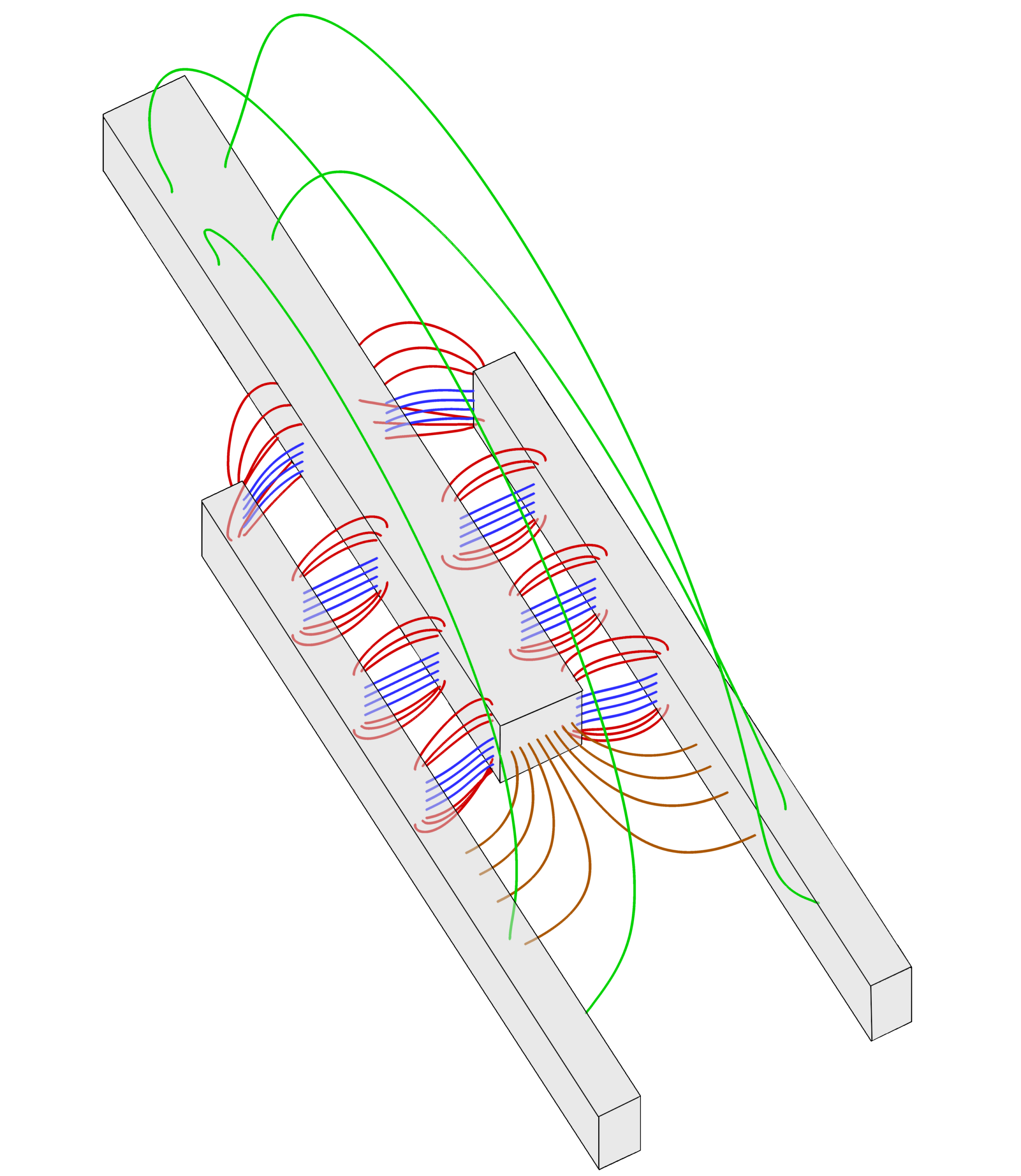

These field lines also reveal something the simple formula hides: the electric field is not confined to perfectly parallel sidewalls. At the finger ends, fields spread into space. Their forces depend on the precise shape, separation and amount of overlap.
How much motion does a tiny comb produce?
Consider a deliberately simplified numerical design: 100 effective moving fingers, each 10 µm thick, with a 2 µm lateral gap, in air at 20 V. The ideal expression gives
F ≈ 100 × (8.854 × 10−12 F/m) × (10 × 10−6 m) × (20 V)² / (2 × 10⁻⁶ m) ≈ 1.77 µN.
The units work: F/m multiplied by a length ratio and V² gives newtons. If a supporting suspension has a longitudinal stiffness of 1 N/m, and if other forces can be neglected, its static displacement would be x = F/k ≈ 1.77 µm. This is a model calculation, not a measured device specification. Real force depends on the effective number of active sidewalls, end geometry, fabrication tolerances and how the springs are connected.
Notice the scaling. Double the voltage and the force becomes four times larger. Halve the side gap and the ideal force doubles, but making a gap smaller also increases the risk of lateral instability, contact and fabrication defects. More fingers offer greater force at the cost of chip area and parasitic capacitance.
What the ideal formula misses
Nearly constant force applies to motion along the fingers while substantial overlap is maintained. Sideways motion toward a neighboring finger is a different problem. Electrostatic attraction in that direction can increase as one gap narrows. The suspension must therefore be stiff enough laterally and rotationally to keep the teeth aligned.
The field-line image above makes the problem tangible. Fringing fields, the substrate beneath the comb, and unequal upper and lower fields can produce forces in unintended directions, including out-of-plane levitation. The 1990 Berkeley research by William Tang describes fabricated polysilicon resonators and reports that finger gap had a stronger influence than finger width or length. It also discusses vertical levitation and strategies to reduce it. The lateral-instability analysis by Truong, Le and Halvorsen examines how translation and rotation can lead to pull-in.
Another limitation comes from speed. A comb suspended on springs is a mechanical resonator. At low frequencies, displacement can follow the electrostatic force almost statically; near resonance, the amplitude and phase depend on damping and the quality factor Q. In early polysilicon experiments, researchers observed resonances in the tens of kilohertz. The original 1989 work by Tang, Nguyen and Howe helped establish comb-driven micromechanical resonators. Such devices can serve as actuators, oscillators or sensors, but a high Q can be undesirable when rapid settling is required.
Electrical drive brings its own constraint. Because force is proportional to V², reversing the voltage polarity does not reverse the attraction. Bidirectional control commonly uses opposing comb banks with separately controlled biases. A small alternating voltage superposed on a DC bias also produces a force component at the drive frequency: expanding (VDC + v sin ωt)² gives a term 2VDCv sin ωt as well as a component at 2ω. This is useful for exciting a chosen mechanical resonance.
A useful comparison to simulate
Proposed numerical exercise (not performed): compare a gap-closing actuator and an overlap-varying comb. Choose the comb parameters above and compute its ideal force at 5, 10, 15 and 20 V. Then plot force against overlap from 5 to 30 µm; it should be horizontal in the ideal model. For a gap-closing parallel-plate device, choose a fixed area and plot F = εAV²/(2g²) as its gap falls from 5 to 2 µm. Its attraction rises sharply as the plates approach.
The comparison explains why designers choose comb geometry for comparatively long, controllable in-plane strokes. It does not predict the stability of a fabricated device: add lateral spring compliance, fringe fields and fabrication offsets before making a real design decision. Gaudiello and Lenczner’s two-dimensional model is one route beyond the elementary parallel-plate approximation.
A useful next design question is therefore quite specific: for a fixed chip area and allowable voltage, how many fingers can be added before the gains in axial force are outweighed by the stiffness needed to prevent sideways pull-in? The answer lies in treating the electrode geometry and suspension as one coupled system.
Author
What concrete example would confirm or challenge this article?
Choose a reaction, write a comment, or ask your AI assistant to send a proposal for review. Comments are reviewed before publication.