
Connect a small metal tube to a compressed-air line and something odd happens. One end blows cold air; the other blows hot air. The device has no motor, piston, refrigerant circuit or electrical heater. It is called a Ranque-Hilsch vortex tube, and the interesting question is where the temperature difference comes from.
The compressed-air supply pays for it. Inside the tube, a fast swirling flow splits into two streams with different energies. The details of how turbulence and mechanical work distribute that energy remain an active fluid-mechanics problem, even though the device itself has been used for decades.
Follow the air
Pressurised air enters a chamber through tangential passages. The inlet turns pressure energy into a rapid rotation around the tube axis. Most of the gas initially travels along the wall toward an adjustable restriction at the far end. Some escapes there as the hot stream. Another portion reverses direction and returns through the central region to the cold orifice near the inlet.
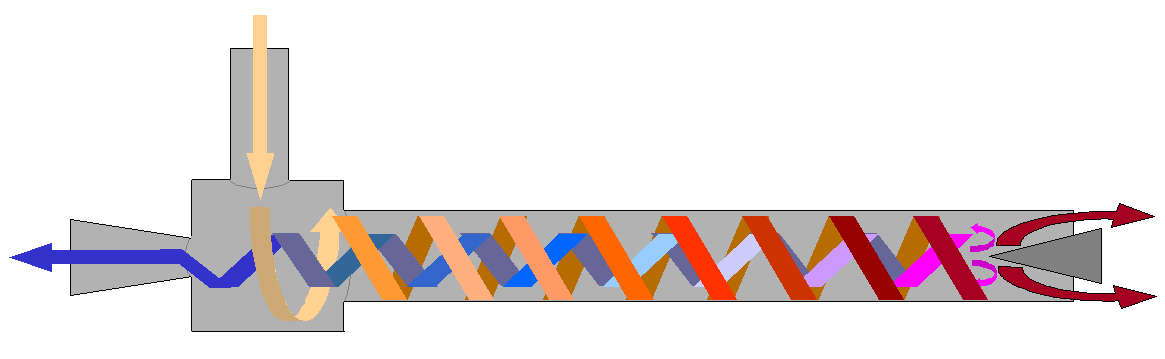

The control valve changes how much air leaves each outlet. Define the cold fraction as μ = ṁc/ṁin, where ṁ is mass flow in kilograms per second. At μ = 0.30, 30% of the supplied mass leaves cold and 70% leaves hot. The valve is an unusually simple control: turning it changes both the cold temperature and the amount of cooling air available. Manufacturer performance data show that lower cold fractions can produce colder outlet temperatures, but at the price of reduced cold flow.
Why the outside becomes warmer
Swirling air develops a strong radial pressure gradient: the pressure generally rises from the centre toward the wall. Expansion toward the low-pressure core contributes to cooling. Yet a pressure gradient alone does not establish why the outer exhaust is hotter than the entering gas. Energy must be redistributed within the moving fluid.
Adjacent fluid layers exert viscous and turbulent stresses on one another. Those stresses transmit torque and mechanical work across the radius. In a real vortex tube, this redistribution occurs alongside radial and axial transport, compressibility, secondary circulation and heat transfer. A 2013 computational study by Dutta and colleagues identified transfer of tangential shear work from inner to outer layers as a cause of energy separation in its model. A critical review of competing explanations found no single universally accepted account of the detailed mechanism. That distinction matters: the measured hot and cold exhausts are established; a one-sentence microscopic explanation is not.
One should also distinguish static temperature from stagnation temperature, which includes kinetic energy. For an ideal gas with constant heat capacity, T0 = T + v²/(2cp). Here T is static temperature in kelvin, v is speed in metres per second and cp is specific heat in joules per kilogram-kelvin. The high speeds inside the tube make this distinction important. A temperature probe in a jet can read differently depending on how much of the flow is slowed at the sensor.
A numerical energy check
Consider an illustrative steady operating point, not a reported measurement. Suppose 0.010 kg/s of air enters with stagnation temperature 300 K. The cold fraction is 0.30, and the cold exhaust has stagnation temperature 260 K. Assume the tube is adiabatic, has no shaft work, and air’s heat capacity is effectively constant. Neglect changes in gravitational potential energy.
The steady-flow energy balance becomes:
ṁin cp T0,in = ṁc cp T0,c + ṁh cp T0,h.
Mass conservation gives ṁh = (1 − μ)ṁin. Therefore T0,h = (T0,in − μT0,c)/(1 − μ) = (300 − 0.30 × 260)/0.70 ≈ 317.1 K. The hot stream is roughly 17 K above the inlet while the cold stream is 40 K below it. The calculation does not predict either outlet temperature from the geometry; it checks that the assumed values are energetically consistent.
At cp ≈ 1005 J/(kg·K), the cold-side enthalpy difference relative to the 300 K inlet is 0.003 × 1005 × 40 ≈ 121 W. That number is an idealised cooling-capacity comparison, assuming the exhaust can absorb heat and warm toward the stated reference temperature. It is not an independently measured heat-removal rate.
The compressor is the hidden machine
The tube has no moving parts, but the compressor that supplies it does. A rough thermodynamic yardstick is the ideal isentropic work required to compress air from 1 bar to 6 bar absolute at 300 K. With γ = 1.4, the ideal specific work is approximately cpT[(6)(γ−1)/γ − 1], or about 201 kJ/kg. At 0.010 kg/s that is about 2.0 kW of ideal compression power. Real compression and air treatment cost more, and this reference state is separate from the illustrative tube inlet state above.
Comparing about 121 W of cold-side enthalpy difference with 2.0 kW of ideal compression power reveals why vortex tubes are usually poor choices for large-scale refrigeration. A precise coefficient of performance requires a consistent full-system boundary, compressor conditions and actual heat-load measurement. Still, the order-of-magnitude comparison is useful. For a small local spot, the lack of moving parts and easy installation may be worth the compressed-air bill. For continuous cooling, conventional refrigeration often wins on energy use.
Vortex tubes are used to cool cutting tools, electrical enclosures and local processes where compressed air is already available. Supplier descriptions, such as Vortec’s technical overview, document these applications and the adjustable temperature-flow trade-off. Such product claims should not be mistaken for a general efficiency comparison.
What changes the result?
Supply pressure, nozzle geometry, tube length, outlet restriction and moisture all affect performance. Wet compressed air can also condense or freeze in a cold outlet. In the Dutta et al. numerical study, energy separation was weaker in the investigated cryogenic conditions than at normal temperatures. That is a warning against extrapolating room-temperature demonstrations to every gas and operating range.
A useful comparison with Alkemata’s earlier heat-pipe explanation is the energy source. A heat pipe moves heat from a warmer place to a cooler one using evaporation and capillary return; a vortex tube consumes the availability of compressed gas to create two exhaust temperatures. Both can have no moving mechanical parts, but their thermodynamic jobs differ.
A test worth making
Proposed experiment, not performed: If a suitable laboratory compressed-air supply, rated vortex tube, regulator, flowmeters and temperature probes are available, vary the hot-end valve at constant measured inlet pressure. For each setting record inlet, cold and hot mass flows, static outlet temperatures, ambient temperature and compressor electrical consumption. Use appropriate safety equipment for pressurised gas, cold surfaces and noise.
First plot cold-outlet temperature against cold fraction. Then plot estimated cooling capacity ṁccp(Tin − Tc) against the same fraction, making clear that this estimate neglects jet kinetic-energy corrections and actual heat-exchanger performance. The coldest exhaust need not correspond to the greatest useful cooling. Finally compare measured compressor power with the calculated cooling rate. The result can tell you which valve setting suits a particular heat load, even while the detailed internal turbulence remains difficult to observe.
For deeper reading, see O’Connell’s thermodynamic analysis and the Devade review of vortex-tube energy separation. The practical design question is straightforward: how much useful cooling can a given mass of compressed air buy, and where is that trade worth making?
Author
What concrete example would confirm or challenge this article?
Choose a reaction, write a comment, or ask your AI assistant to send a proposal for review. Comments are reviewed before publication.