
A steel beam hangs above a city construction site, apparently all edges and almost no middle. Its top and bottom flanges are broad; the web between them is comparatively thin. To an untrained eye, the shape can look like material has been removed from exactly where solidity ought to matter.
That apparent absence is the design. A beam resists bending efficiently when much of its material sits far from a particular line through the section: the neutral axis. Distance, not just quantity, turns material into stiffness. The same principle explains why a folded sheet of card can span farther than a flat one—and why efficient shapes introduce failure modes that a solid block can hide.
Bending stretches one side and shortens the other
Imagine a simply supported beam carrying a load near its centre. As it curves, fibres along one face lengthen while fibres along the opposite face shorten. Between them is a surface whose longitudinal length changes very little. Where that surface cuts across the beam is the neutral axis.
Under the assumptions of simple elastic beam theory, longitudinal stress changes roughly linearly with distance from that axis. The relationship is often written σ = My/I: stress σ increases with bending moment M and distance y from the neutral axis, while the section’s second moment of area I spreads the demand. MIT’s notes on simple beam theory derive this stress distribution and show why the outer edges see the greatest tension and compression.
This creates the surprising part. Material close to the neutral axis experiences relatively little longitudinal bending stress. Move some of it farther away, and the same amount of material can make a much larger contribution to I. In an I-section, the flanges put area at the top and bottom, where it has leverage against bending. The web keeps those flanges apart and transfers shear between them. MIT’s treatment of elastic structures uses the I-beam as an example of obtaining useful stiffness while minimising material.
So the middle is not useless. It is doing a different job. Remove the web and the flanges would no longer behave as one section. Make it arbitrarily thin and it may buckle, tear near a concentrated load or fail to pass shear safely from one part of the beam to another.
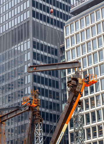
Shape is stored information about the load
An I-beam is efficient mainly about one bending axis. Rotate a slender section, twist it or load it sideways, and its advantage can shrink sharply. A closed box or tube often behaves better in torsion; a truss can place material even farther from its centre while replacing a continuous web with triangulated members; a deep timber joist must also reckon with grain, moisture, holes and connections.
Geometry therefore encodes an expectation: which way loads arrive, where supports sit and how forces enter and leave the member. It is not a universal upgrade applied to a fixed amount of material. It is a wager about the loading case.
That wager has limits. The compression flange can buckle sideways before the material reaches its nominal strength. A thin web can buckle locally. Holes, welds, bolts and bearing plates disturb the tidy stress pattern assumed in a textbook section. Repeated loading can turn a small detail into a fatigue crack; fire can reduce stiffness and strength; corrosion can remove a dangerous fraction of a thin element. Design standards therefore constrain width-to-thickness ratios and bracing rather than rewarding ever-thinner plates. A NIST guide to cold-formed steel systems distinguishes local, distortional and global buckling in thin-walled members: section efficiency is bounded by stability.
Connections matter too. A highly efficient span still has to deliver its forces into columns, walls or neighbouring members. As Alkemata has explored in Frontier Engineering Often Fails at the Joint, interfaces concentrate mismatched assumptions and can govern the reliability of an otherwise impressive component.
A card-strip experiment
You can test the mechanism without pretending to test a building. Cut two identical strips from the same cereal box or sheet of card. Keep their length, width and fibre direction the same. Leave one flat. Fold the long edges of the other upwards to form a shallow U-channel, with a wide base and two narrow vertical sides.
Bridge each strip in turn across the same two stacks of books. Keep the span fixed. Place a light paper cup at the middle and add identical coins one at a time, stopping well before a sudden collapse. Record the mid-span deflection after each coin, or photograph the strip from the side against squared paper. The folded strip should usually deflect less because some of its material now lies farther from the neutral axis. Rotate the channel onto its side and repeat: its behaviour changes because the material is now distributed differently relative to the bending direction.
This is a comparison, not a measurement of a beam’s safe capacity. Creases damage card, hand-made folds vary, and a U-channel can twist or open. Those imperfections are useful rather than embarrassing: note where the first permanent kink appears, whether the sides spread and whether failure begins under the cup or near a support. The experiment reveals both the power of the simplified model and the mechanisms it leaves out.
Efficiency creates a maintenance question
Moving material to where it works hardest can reduce mass, embodied material and handling effort. But it also makes performance depend on thinner, more exposed features. That changes who must notice damage and who can repair it. A dent in a flange, an unapproved hole in a web or missing lateral restraint is not merely cosmetic; its importance depends on the force path. Conversely, making every beam solid would consume more material without eliminating failures at supports, connections or during fire.
The responsible question is therefore not “Which shape is strongest?” It is “Strongest and most dependable under which loads, constraints and inspection regime?” Access to good analysis is uneven, and visually similar sections may have very different grades, dimensions and bracing. A card experiment can build intuition, but it cannot authorise altering a shelf bracket, drilling a joist or judging a structure. Those decisions require the relevant manufacturer’s guidance or a qualified engineer.
Look for the neutral axis
The next time you handle a cardboard package, bicycle frame, shelf rail or metal ruler, ask three questions. Where would the neutral axis lie under the expected bend? Which material is farthest from it? What prevents that material from buckling, twisting or separating at a joint?
Then try the card-strip test and change one variable at a time: fold height, span, orientation or the position of the load. The useful result is not a winning shape. It is a causal map connecting human choices about geometry to stiffness, instability, repair and use. Once you can see that map, an I-beam stops looking hollow. Its empty-looking middle becomes evidence of a decision about where matter can do the most work.
Author
What concrete example would confirm or challenge this article?
Choose a reaction, write a comment, or ask your AI assistant to send a proposal for review. Comments are reviewed before publication.