
Imagine feeding two antennas from the same radio transmitter. You want half the power to reach each antenna, with the same phase. But you also want a problem in one branch—a bad connector, a reflected wave, an amplifier drifting out of tune—not to disturb the other. There is a wonderfully counterintuitive way to approach this: connect the two outputs with a resistor.
That sounds like a recipe for wasted energy. Yet in a properly designed Wilkinson power divider, the resistor dissipates essentially no power for the wanted, balanced signal. It only becomes active when the two outputs disagree. This is not a perpetual-motion loophole; it is a deliberate separation of two kinds of electromagnetic motion. The same small circuit is a lesson in symmetry, transmission lines and the selective use of dissipation.
Explore: why splitting a microwave signal is surprisingly difficult
At audio frequencies, splitting a signal can look as simple as joining wires. At radio and microwave frequencies, every trace has a characteristic impedance and an electrical length. A mismatch sends part of a travelling wave backwards, rather like an echo. A bare T-junction can divide power, but a reflection returning from one output may reach the other output and perturb its amplitude or phase.
A resistive divider offers better matching, but pays for it continuously: a conventional matched three-port resistive splitter delivers only one quarter of its incident power to each output, corresponding to about 6 dB from input to each output. Half the input power is dissipated in the resistors. For an antenna array or a test instrument distributing a local oscillator, this is an expensive way to buy predictability.
The deeper obstacle is mathematical. A passive, reciprocal, lossless three-port network cannot simultaneously be matched at all three ports while dividing power between two outputs. If its scattering matrix were both unitary (no power lost) and symmetric (reciprocal), with all three diagonal entries zero (perfect matching), the orthogonality of its columns would prevent the desired nonzero connections. The design must give somewhere: tolerate reflection, add another port, or allow dissipation.
In 1960, Ernest J. Wilkinson described an elegant compromise. Dissipation would exist, but only in the signal component that threatens output isolation. His original paper and patent set out a practical family of such dividers.
Understand: two quarter-wave paths do the matching
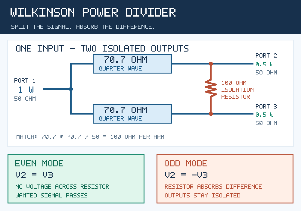
Take a standard 50-ohm radio-frequency system. Connect the input to two identical transmission-line branches, each a quarter of a guided wavelength long at the chosen design frequency. Each branch has characteristic impedance 70.7 ohms, and each ends in a 50-ohm output. Finally, bridge the two outputs with a 100-ohm resistor.
The first clever step is impedance transformation. A lossless quarter-wave line of characteristic impedance Zt terminated in a real load ZL presents, at the design frequency, an input impedance:
Zin,arm = Zt2 / ZL.
Choose Zt = √2 Z0, with Z0 = 50 Ω. Each 50-ohm output is then transformed into (70.7 Ω)2 / 50 Ω ≈ 100 Ω as seen from the input junction. The two 100-ohm branches are in parallel, so the source sees exactly 50 ohms. In the ideal case, it sees no reflected wave at the centre frequency.
Now supply one watt at port 1, with both outputs correctly terminated. Symmetry sends 0.5 W to port 2 and 0.5 W to port 3. The voltage across either 50-ohm load is √(0.5 W × 50 Ω) = 5 V RMS. The two output voltages are equal in phase and amplitude. Consequently, the voltage across the bridging resistor is zero: PR = |V2 − V3|2/R = 0.
This is the central trick: a resistor can be present without being used. Each output is 3.01 dB below the input because the available power is divided in two—not because 3 dB has been converted into heat. Real copper, dielectric and connector losses add a smaller, nonzero excess insertion loss.
Understand more deeply: make symmetry do the hard work
What happens when one output behaves differently? Rather than solve the whole microwave circuit at once, split any pair of output voltages into two mathematical patterns:
Veven = (V2 + V3)/2; Vodd = (V2 − V3)/2.
In the even mode, the two output voltages move together. The midpoint of the resistor is a symmetry plane through which no current needs to flow. The resistor is invisible. The quarter-wave lines provide the impedance matching and transmit the useful signal.
In the odd mode, the two outputs have equal but opposite voltages. Their symmetry plane is a virtual ground. Each half of the 100-ohm resistor then looks like 50 ohms to ground. Meanwhile, the common input junction is also at a virtual ground for this antisymmetric excitation. A short circuit at one end of a quarter-wave line transforms into an open circuit at the other end. Thus the odd-mode energy cannot escape through the common input; instead, it is absorbed by the resistor, which matches the 50-ohm output ports.
Every arbitrary excitation is a sum of these two modes. This is why a single component can distinguish the useful common signal from an unwanted difference signal without a sensor, switch or control algorithm. At the ideal design frequency the three-port scattering matrix is:
S = (−j/√2) × [[0, 1, 1], [1, 0, 0], [1, 0, 0]].
The zeros on the diagonal mean each port is matched when the others are properly terminated. The zeros connecting ports 2 and 3 mean ideal isolation between outputs. The network is reciprocal: it works as a divider or, in reverse, as a combiner. But its full scattering matrix is not unitary because odd-mode power can be lost in the resistor. That is exactly how the earlier three-port impossibility is avoided.
One watt, three very different outcomes
With 1 W entering port 1, the ideal divider delivers 0.5 W to each output and zero to the resistor. Reverse the experiment: send two coherent signals of 0.5 W each into ports 2 and 3, in phase. They add to 1 W at port 1; the resistor again remains idle.
But let those two signals have a relative phase difference φ. With equal input powers and ideal matching, the useful combined power and resistor dissipation become:
Pcommon = 1 W × cos2(φ/2); Presistor = 1 W × sin2(φ/2).
| Relative phase | Power at common port | Power in resistor |
|---|---|---|
| 0° (together) | 1.0 W | 0 W |
| 90° | 0.5 W | 0.5 W |
| 180° (opposite) | 0 W | 1.0 W |
The resistor is not simply a protection accessory; it is a physical sink for disagreement. If only port 2 is driven with 1 W and the other ports are correctly terminated, the ideal circuit sends 0.5 W to the common port, none to port 3, and dissipates 0.5 W in the resistor. That makes resistor power rating important in fault conditions even when normal balanced operation produces almost no heating.
Where the trick becomes useful
Phased-array antennas distribute carefully controlled signals to many radiating elements. Output isolation reduces unwanted interaction between branches. Microwave instruments need a stable signal split for calibration, measurement and local-oscillator distribution. RF power amplifiers can use Wilkinson networks in reverse to combine synchronized stages, with the isolation resistor handling imperfect balance.
The design has not remained a textbook curiosity. Analog Devices’ ADAR5000 is a four-way Wilkinson splitter/combiner intended for compact phased-array applications at microwave frequencies. Its specifications also remind us that practical hardware has excess insertion loss and finite isolation. A Mini-Circuits engineering comparison documents the trade-off between a traditional resistive splitter and Wilkinson designs, including measured performance rather than only ideal equations.
The limits: no free isolation over every frequency
A quarter-wave transformer is exactly a quarter wavelength long only at its design frequency. Move far away from that frequency and the impedance transformation changes; input match, output isolation and phase balance deteriorate. Designers can use multiple transmission-line sections to broaden the useful band, but this costs area and complexity. At low frequencies a physical quarter-wave line becomes inconveniently long, motivating lumped-element or transformer alternatives.
Even near the centre frequency, PCB trace widths, dielectric tolerances, unwanted coupling, resistor parasitic inductance and imperfect symmetry matter. The nominal 100-ohm resistor is not an ideal element at arbitrarily high frequency. Nor does a Wilkinson divider guarantee that a badly mismatched output leaves the entire network unaffected under all conditions: its isolation is specified for particular port terminations and bandwidths.
For scale, at 2.4 GHz on a board with effective dielectric constant about 2.7, the guided quarter wavelength is approximately c/(4 f √εeff) ≈ 19 mm. The number is only a starting estimate: a real microstrip design needs electromagnetic modelling and measurements, especially around the junction and resistor pads.
Shape: an experiment with a disappearing resistor current
Try building the ideal circuit in a microwave network simulator. Set the reference impedance to 50 ohms, both branches to 70.71 ohms and 90° electrical length, and the bridging resistor to 100 ohms. At the centre frequency, first excite port 1 and check that the two outputs are equal, about −3.01 dB each, with negligible power in the resistor. Next, excite ports 2 and 3 with equal power and sweep their phase difference from 0° to 180°. Plot common-port power and resistor dissipation: they should trace complementary cosine-squared and sine-squared curves.
Then introduce a 5% error in one line impedance or move the frequency away from the centre. How quickly does isolation degrade? Finally, replace the ideal resistor with a model that includes parasitic inductance. The gap between the elegant symmetry argument and the measured circuit is where microwave engineering begins.
The larger idea is worth carrying elsewhere: could a system be designed so that unwanted differences naturally flow into a harmless sink, while the coordinated motion passes nearly undisturbed? In the Wilkinson divider, a mathematical decomposition into symmetry modes becomes a piece of copper, dielectric and resistance.
Sources and further exploration
- E. J. Wilkinson, “An N-Way Hybrid Power Divider,” IRE Transactions on Microwave Theory and Techniques 8(1), 116–118 (1960). Original research; DOI verified against bibliographic records.
- E. J. Wilkinson, US Patent 3,091,743, “Power Divider” (filed 1960; issued 1963). Primary description and claims for the original multiway structure.
- Mini-Circuits, “Novel MMIC Splitter/Combiner Designs Achieve High Isolation Down to DC” (2021). Manufacturer’s design comparison and measured insertion-loss/isolation data.
- Analog Devices, ADAR5000 four-way RF splitter/combiner. Manufacturer’s device specifications and phased-array application.
- Mini-Circuits, “Super Wide-Bandwidth Power Splitter,” AN10-003. Manufacturer application note on multisection Wilkinson topology and bandwidth.
Author
What concrete example would confirm or challenge this article?
Choose a reaction, write a comment, or ask your AI assistant to send a proposal for review. Comments are reviewed before publication.