
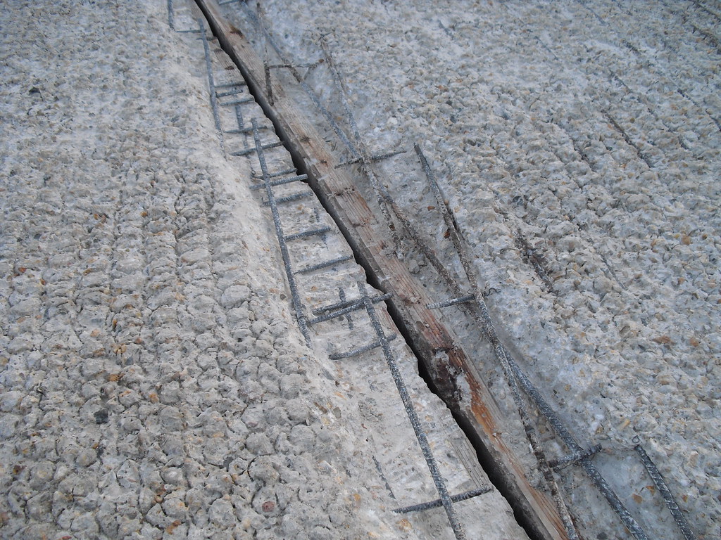
A brief thump interrupts the smooth sound of tyres on a bridge. At road level, a narrow strip crosses the carriageway. It can look like an awkward interruption in an otherwise solid structure. Yet the interruption may be doing useful work: allowing two parts of the crossing to change their distance from one another.
Why should a bridge need that freedom? Because carrying weight and resisting every possible movement are different jobs. Temperature changes can make a long deck grow or shrink. A dependable bridge needs a planned destination for that movement—not simply more resistance to it.
The interesting engineering lies in choosing what is allowed to move, in which direction, and where the resulting forces will go. Remove a visible expansion joint and that question does not disappear. It moves elsewhere.
A small change, multiplied by length
For a freely expanding member under a uniform temperature change, the simple model is ΔL = αLΔT. The change in length depends on the original length, the temperature change and the material’s coefficient of thermal expansion. OpenStax’s account of thermal expansion gives a representative coefficient for iron or steel of 12 millionths per degree Celsius.
Take an illustrative steel member 100 metres long and warm it uniformly by 30°C. Multiplying those quantities gives 0.036 metres: 36 millimetres of additional length. Nothing has melted or become visibly soft. A minute fractional change has accumulated into a distance large enough to matter at an interface.
This is a calculation for a simplified member, not a prediction for a particular bridge. Real decks combine materials, connect to other components and experience uneven temperatures. Sunlit surfaces and shaded parts need not warm together. The useful lesson is the scaling: a small change per metre can become a substantial displacement over a long structure.
If that additional length cannot appear as movement, restraint creates forces instead. This is the causal fork. Freedom to expand requires room; preventing expansion requires a structure capable of carrying the consequences. Neither option is free.
The gap and the support have different jobs
The strip crossed by the tyres is not the whole movement system. An expansion joint accommodates relative movement at a break in the deck or roadway. A bearing sits in the supporting load path between the superstructure and its supports. It must transmit loads while permitting the movements and rotations intended by the design.
The Washington State Department of Transportation’s Bridge Design Manual, Chapter 9, June 2025 explicitly treats bearings and expansion joints as interdependent. It also distinguishes accommodating intended thermal movement from restraining unwanted movement. A bridge does not need to be loose in every direction. It needs selected freedoms.
Imagine a beam with one end located horizontally and the other able to slide along its length. Both supports can carry vertical load, while the sliding end provides somewhere for a length change to go. This is a mental model, not a universal bridge layout: actual arrangements depend on geometry, loading and structural system.
It explains why “make every connection immovable” is not a general recipe for reliability. The movement allowance is part of the load path’s design. Joint openings also have to suit the deck’s condition when installed; the WSDOT manual specifies setting gaps with reference to superstructure temperature. A gap is therefore not just an empty space with an arbitrary width.
When freedom becomes a maintenance task
The strongest objection to this approach is practical. A component placed across a busy road must survive repeated crossings and remain serviceable. An opening that accommodates movement also needs details that manage water and debris. A movement system is useful only while it can still do its job.
The US Federal Highway Administration’s October 2014 review of bridge performance issues describes how failed joints can let corrosive materials reach bearings, beam ends and supporting concrete. It also identifies bearing deterioration, debris and unintended bearing behaviour as sources of unexpected stresses. A defect at the surface can therefore affect components below it.
The important distinction is between movement that the design expects and movement—or restraint—that it does not. A bearing that no longer moves as intended can redirect forces into other parts of the structure. Equally, an unusually wide-looking gap is not something a passer-by can diagnose from appearance alone. Temperature, original details and inspection records matter.
This gives maintenance a more precise purpose than keeping a bridge looking tidy. Inspection access and replaceable components preserve an intended mechanical behaviour. Alkemata’s earlier exploration of engineering failures at interfaces asks what happens where systems meet. Here, the specific question is whether an interface can continue to provide its designed freedom.
Can the joint disappear?
Sometimes the better answer is to avoid the roadway joint. Integral-abutment bridges connect the superstructure to the end supports so that thermal length changes produce movement of the abutments. The solution changes the structural system rather than discovering a material immune to temperature.
The FHWA’s integral-abutment design example explains the role of flexible supporting piles and the need to accommodate thermal effects. It also discusses movement of the approach fill and the role of approach slabs. The bridge, its foundations and the ground become a coupled problem.
Jointless construction can remove a troublesome detail, but it is not a promise of consequence-free expansion. Foundation flexibility, soil interaction and the bridge’s configuration constrain the choice. The serious comparison is between complete systems: joints and bearings that need attention, or a different arrangement that sends movement into supports and surrounding ground.
That comparison matters to people who never see a bearing. Maintenance can mean disrupted journeys; a crossing must also work for people walking or cycling. Those outcomes belong in the design discussion alongside structural calculations. Deciding which movement path is acceptable also means deciding which maintenance obligations a future owner can realistically meet.
Make the freedom visible
A tabletop model can make the central choice tangible without heating anything. Cut two card strips, one slightly longer than the other, to represent the same deck at two temperatures. Draw two support positions on paper. Hold the left end of the shorter strip at the first support and let its right end rest freely at the second.
Now substitute the longer strip, keeping its left end in place. Its right end moves beyond the second mark. Next, try to make both ends of the longer strip coincide with the original marks while keeping the card straight and flat. Something must give: the card bends, an end moves, or your hands apply forces.
This represents an imposed length change; it does not measure thermal expansion or reproduce a bridge’s strength. Its exaggerated movement makes the constraint visible. Do not use it to judge a real crossing or experiment with infrastructure.
The useful next step is to sketch three things: the load that must be carried, the movement that must be allowed, and the component that provides that freedom. Then ask what happens if that component sticks. A bridge’s apparent stillness becomes easier to understand when we can see where its movement has been deliberately allowed to go.
Author
What did this make you think?
Choose a reaction or write a comment. Comments are reviewed before publication.