
A spacecraft can be in blazing sunlight on one side and facing deep space on the other. Its electronics still need a narrow operating-temperature range. A conventional solution would circulate coolant with a mechanical pump. But one of the most elegant thermal devices contains no motor, no electronics, and often no moving solid parts at all. A sealed tube, a little working fluid, and a porous lining can move substantial heat from a hot component to a distant radiator.
The ingenious part is not simply that liquid boils. It is that evaporation transports energy while surface tension pumps the liquid back. The two jobs cooperate to make a passive circulation system: a heat pipe.
Explore: why a solid bar is not enough
Heat naturally flows from a hotter region to a cooler one. A copper bar can carry it by conduction, but maintaining a large heat flow along a long, thin bar requires a temperature gradient. Fourier’s law gives a simple one-dimensional estimate: Q̇ = k A ΔT / L, where k is thermal conductivity, A the cross-section, and L the length.
For a thought experiment, take a copper rod 0.5 m long with a 1 cm² cross-section, a conductivity of roughly 400 W/(m·K), and a 10 K temperature difference. The formula yields only about 0.8 W. It is a deliberately slender rod, not a universal comparison of real cooling assemblies, but it exposes the problem: making a longer thermal connection quickly becomes expensive in mass or temperature drop.
Could a fluid carry energy instead? Yes—but an ordinary liquid loop usually needs a pump to circulate it. A heat pipe exploits a different carrier: latent heat, the energy absorbed when a liquid turns into vapor and released when vapor condenses. In a suitable sealed device, the vapor can transport a great deal of energy while its pressure and temperature vary relatively little.
Understand: two streams moving in opposite directions
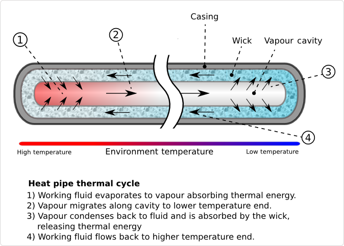
Look at the diagram. At the evaporator, heat from an electronic component makes the working fluid evaporate. The resulting vapor flows through the central passage toward the cooler condenser. There it gives up latent heat to a cold surface and turns back into liquid. The liquid returns along the porous wick lining the tube, moving opposite to the vapor.
Why does the liquid return? Inside the wick, a liquid-vapor interface curves into tiny pores. Surface tension creates a pressure jump across that curved interface. The evaporator’s menisci become more strongly curved as liquid is consumed, establishing a capillary-pressure difference that draws liquid back from the condenser. The wick is therefore a capillary pump with no rotating parts. The temperature difference drives the heat flow and phase changes; surface tension sustains the liquid circulation.
It is tempting to imagine the vapor “pushing” all the liquid back. That misses the important distinction. Vapor pressure drives vapor toward the condenser, while the pressure difference maintained at the liquid-vapor menisci provides the pumping head for liquid return through the wick. A functioning heat pipe balances both flow paths.
The first equation: energy rides on a phase change
If the vapor carries mass at a rate ṁ and the latent heat of vaporization is hfg, then, to a useful first approximation, Q̇ ≈ ṁ hfg. Sensible heating, conduction, and losses can matter in a real design, but this captures the central trick.
For water near its ordinary boiling point, hfg is about 2.26 MJ/kg. Moving 100 W by phase change therefore requires only ṁ ≈ 100 / 2,260,000 = 4.4 × 10⁻⁵ kg/s, or about 0.044 grams of vapor per second. The operating pressure and temperature of a water heat pipe need not be atmospheric, so this is an illustrative calculation rather than a design rating.
Notice what has happened: the energy is not primarily conducted through the metal wall over the full length. It is carried by molecules that evaporate at one end and condense at the other. The same small inventory of fluid can repeat the cycle continuously.
The second equation: a meniscus becomes a pump
For an idealized circular pore of effective radius r, the maximum capillary-pressure scale is Δpcap ≈ 2γ cosθ / r. Here γ is liquid surface tension and θ the contact angle. Real wicks have complicated interconnected pores, so this is a design intuition rather than a complete pore-network model.
Take a wetting liquid with surface tension 0.07 N/m, an approximately zero contact angle, and a pore radius of 10 micrometers. The pressure scale is 2 × 0.07 / 10−5 ≈ 14,000 Pa: roughly 14 kPa. That is a substantial pressure difference produced by a tiny curved interface, without any motor.
But this leads to the most interesting engineering compromise. Smaller pores increase the possible capillary pressure—yet they also resist liquid flow more strongly. A wick with microscopic pores may pump against a large pressure difference while delivering too little fluid to keep the evaporator wet. The best wick is not simply the one with the smallest pores. Its pore size, permeability, thickness, wettability, and geometry must work together.
In simplified form, sustained operation requires Δpcap,max ≥ Δpliquid + Δpvapor + Δpgravity, with the gravity term taken with the appropriate sign for orientation. If the available capillary head cannot cover the hydraulic losses and any adverse elevation, the evaporator can dry out. This is the capillary limit, one of several possible heat-pipe operating limits.
Why this trick matters in space
On Earth, some cooling devices rely on gravity to return condensed liquid. In orbit, that strategy is unreliable. A wick-based heat pipe can work in microgravity because capillary forces do not need a “down” direction. NASA describes heat pipes as passive spacecraft thermal-control components: heat enters near equipment, vapor travels to a cooler section, and the wick returns liquid. The cold end must still reject the energy—often through a radiator that emits thermal radiation into space. A heat pipe transports heat; it does not make heat disappear.
There is also an important distinction between a conventional heat pipe and a loop heat pipe. In a conventional design, vapor travels down the central channel while liquid returns through the surrounding wick. In a loop heat pipe, vapor and liquid typically travel in separate lines, and a porous evaporator supplies the capillary pumping pressure. This arrangement can transport heat over greater distances and offer design flexibility, but it brings its own startup, stability, and compensation-chamber challenges. ESA has investigated loop heat pipes for spacecraft electronics and deployable radiators.
Shape: the limits reveal the next design
A heat pipe is not a magical superconductor for heat. Its performance depends on working-fluid selection, temperature, orientation, wick permeability, vapor velocity, and how effectively the condenser rejects energy. At some conditions the liquid supply cannot keep up (capillary limit); at others, vapor flow can encounter viscous or sonic restrictions, liquid can be entrained into the vapor stream, or boiling behavior can disrupt the wick. Freezing, non-condensable gases, corrosion, and incompatible materials may also matter.
Designers therefore choose the working fluid and container together. Water-copper devices are common in suitable terrestrial temperature ranges; ammonia-aluminum systems are widely used for spacecraft thermal control. Neither pairing is universal. The best choice depends on operating temperature, pressure, materials compatibility, and mission constraints. A heat pipe is passive in operation, not effortless in design.
The cleverest extension may be to change the plumbing rather than the fluid. Separating vapor and liquid lines can reduce some of the counterflow restrictions of a traditional heat pipe. NASA research has examined the capillary limit in loop heat pipes with multiple evaporators, showing that exceeding the nominal limit need not always cause an abrupt shutdown: the system may settle into a less favorable thermal state. That subtlety matters when designing resilient equipment, not merely optimizing a laboratory peak performance.
A small experiment worth trying
Imagine two identical metal plates connected to a heat source at one end and a heat sink at the other. In one, heat crosses only by conduction. In the other, a sealed two-phase channel and wick redistribute it. Plot temperature versus distance as the heat input rises. What happens when you gradually tilt the assembly against gravity, or when the cold-end temperature rises? At which point does the capillary-pressure budget fail?
A safer desk experiment is a spreadsheet rather than a homemade pressure vessel: vary pore radius in 2γ/r, then separately estimate how the wick’s flow resistance changes. You will discover a design tension: increasing the driving pressure can simultaneously make the return path harder to traverse. This is an invitation to explore hierarchical wicks—fine pores where pressure is needed, larger channels where flow must be easy.
That is the broader lesson. A clever engineering system does not necessarily eliminate the energy gradient or the physical constraints. It assigns different physical mechanisms to the jobs they do best: evaporation carries the heat; vapor flow carries the mass outward; capillarity brings liquid home. What other systems could become simpler if we stopped asking one mechanism to do every job?
Sources and further exploration
- NASA, State of the Art of Small Spacecraft Technology: Thermal Control — conventional heat-pipe construction and spacecraft applications.
- NASA Technical Memorandum 2019-220147 — capillary pumping, flow pressure balances, and distinctions between traditional and loop heat pipes.
- NASA Technical Reports Server: Capillary Limit in a Loop Heat Pipe with Dual Evaporators — experimental evidence on operating limits and degradation.
- European Space Agency: A Mini Hybrid Capillary Pumped Loop — electronics thermal-management applications.
- Wikimedia Commons: Heat Pipe Mechanism — explanatory diagram and license.

