
A nick appears beside a hole in a plastic handle. The object still looks almost whole; the missing material is negligible. Yet the next hard pull sends a tear from that precise point. The important question is not simply how much material was lost. It is how the flaw redirected force.
A small notch can decide where something breaks because stress does not remain evenly distributed around abrupt changes of shape. A smooth curve spreads the disturbance. A sharp tip concentrates it into a much smaller region. Fracture mechanics turns that local effect into a practical way of thinking: inspect geometry, loading and material together, rather than treating every scratch or hole as equivalent.
Force finds the sharpest route
Imagine pulling a plain strip of material from both ends. Far from the grips, the average tensile stress is the force divided by the strip’s cross-sectional area. If the strip is uniform, that average is a useful first description.
Now cut a hole in it. The load cannot pass through empty space, so the internal force paths bend around the hole and crowd near its boundary. Engineers call the resulting local magnification a stress concentration. A NIST guide to fractography uses a circular through-hole as its introductory example: even a smooth hole in a broad plate under tension produces a maximum local stress about three times the remote stress in the idealised case.
That factor is not universal. It changes with the shape and size of the opening, the width of the part, the direction of loading and the material’s behaviour. But the underlying mechanism is durable. A geometric discontinuity makes an otherwise simple stress field uneven.
A sharp notch goes further. As its tip radius becomes smaller, the force is redirected through an increasingly tight turn. In the mathematical ideal of a perfectly sharp crack in an elastic material, the tip stress is not described by one finite concentration factor. Instead, the near-tip stress rises as distance from the tip decreases.
From stress concentration to fracture
Fracture mechanics therefore uses a different quantity: the stress-intensity factor, usually written K. For a simple opening crack, it has the form
KI = Yσ√(πa)
where σ is the applied stress, a is a measure of crack length and Y accounts for geometry. The square-root relation contains a useful surprise: crack length matters, but so do the surrounding shape and loading. A flaw cannot be assessed from length alone.
If the stress intensity reaches the material’s fracture toughness under the relevant conditions, rapid crack growth becomes possible. Below that point, repeated loading, corrosion or slow subcritical growth may still enlarge a flaw over time. NASA’s linear-elastic fracture-mechanics primer develops this model alongside its limits, including the small plastic zone that forms near a real crack tip.
This is where the intuitive story needs correction. Real materials do not contain infinitely sharp mathematical tips, and many deform plastically before they break. Paper has fibres; metals have grains and residual stresses; polymers may creep; glass is brittle. Thickness, temperature, manufacturing history and loading rate can all change the result. The equation is a model for a defined regime, not a universal failure oracle.
Why rounding helps, and why it is not magic
Designers often round internal corners, add generous fillets or avoid abrupt changes in section because a larger radius can reduce the peak stress. The same logic explains why a punched hole and a razor-like slit of similar depth are not mechanically equivalent. One redirects load around a finite curve; the other creates a much sharper local field.
But “make it round” is not a complete design rule. A hole still removes load-bearing area and concentrates stress. Drilling a round hole at the end of a crack can sometimes blunt its tip temporarily, yet it also creates a new boundary and may leave part of the crack beyond the hole. Whether such a repair is appropriate depends on material, crack geometry, loads and an engineered procedure.
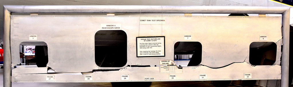
The institutional lesson is as important as the shape. Safety depends on deciding which details must be analysed, inspected and revisited when a design changes. In its account of a 1977 Boeing 707 accident, the US Federal Aviation Administration describes fatigue cracking that initiated at a fastener hole, while design changes had altered stiffness and load transfer. The case helped drive damage-tolerance thinking: assume relevant flaws may exist, then ensure they can be found and managed before they become catastrophic.
That is a stronger idea than simply demanding a “strong material”. As Alkemata’s explainer on why beams put material at the edges shows, distributing material changes how a whole section carries load. Fracture mechanics zooms in further, to the local geometry of a flaw. Dependability comes from a system of shape, material choice, load knowledge, inspection access, intervals, records and responsibility. A detail that cannot be seen or reached may be difficult to keep safe even when its initial calculation is sound.
A paper test of shape
You can make the mechanism visible with ordinary paper, though the result is qualitative and must never be used to judge a real structure.
- Cut at least nine equal paper strips, all in the same orientation on the sheet.
- Leave three intact. In three, use a hole punch at one edge to make a smooth semicircular notch. In the final three, cut a narrow V-shaped notch to roughly the same depth.
- Clamp the top of each strip in the same way. Attach a small binder clip to the bottom and add paper clips one at a time, keeping faces and feet away from the falling load.
- Record the load at failure and where the tear began. Repeat rather than trusting one specimen.
Expect scatter. Paper fibres, imperfect cuts and uneven clamping matter. That variability is part of the lesson: the sharp notch should usually provide a more decisive starting point, but a single dramatic tear is not evidence of a universal numerical factor. Try photographing each notch beside a ruler and grouping the failures by shape.
A worthwhile next step is a “shape audit” of a disposable, non-safety-critical object before it fails: packaging tabs, card prototypes or sacrificial test coupons. Mark holes, slots, sharp internal corners and changes of section; predict where a tear will start; then test only the disposable sample. For buildings, vehicles, tools, pressure vessels or load-bearing parts, observation should lead to the manufacturer or a qualified professional—not a home experiment.
The useful question is no longer merely, “Is there a flaw?” It is: “What does this shape make the load do, how could the flaw grow, and who is responsible for noticing in time?”
Author
What concrete example would confirm or challenge this article?
Choose a reaction, write a comment, or ask your AI assistant to send a proposal for review. Comments are reviewed before publication.