
A satellite is drifting a few degrees away from the direction its camera should face. One solution is to fire a small thruster. That works, but it spends propellant every time the craft corrects its pointing. Another is to accelerate an internal flywheel, forcing the spacecraft to turn in the opposite direction. But there is a more ingenious option for a vehicle that must turn quickly: keep a heavy wheel spinning at nearly constant speed, and gently rotate the axis around which it spins.
That small steering motion can exert a surprisingly large torque on the spacecraft. The device is a control moment gyroscope (CMG), a close relative of the reaction wheel but with a different source of torque. It is used on large platforms such as the International Space Station (ISS), and its appeal is now extending to smaller satellites. In September 2026, ESA described the in-orbit commissioning of compact CMGs that achieved manoeuvres roughly 2.5 times faster than reaction wheels in that particular test. The result is a useful invitation to examine the underlying physics—not a claim that every CMG is always 2.5 times faster.
The trick is to steer a vector instead of repeatedly building and removing its magnitude.
Explore: why pointing is not the same as travelling
A satellite has an orbit, the path followed by its centre of mass, and an attitude, the direction in which its body points. An Earth-observation telescope can follow almost the same orbit while looking at different places on the ground. Rotating the spacecraft is therefore a distinct control problem from changing its orbital trajectory.
With thrusters, attitude control uses a pair of forces or an off-centre force to make a turning moment. With an internal wheel, the forces stay inside the spacecraft. The vehicle and wheel exchange angular momentum. If external torque is negligible, their total angular momentum is conserved. Nothing mysterious pushes against empty space.
In a conventional reaction wheel, a motor speeds the rotor up or slows it down. The spacecraft receives the opposite torque. This is excellent for fine pointing, but generating a large torque may demand a large motor and rapid changes in rotor speed. The CMG takes another route: a motor keeps a flywheel spinning, while a separate gimbal rotates its spin axis. A change in the direction of angular momentum can be just as important as a change in its magnitude.
Understand: a vector that refuses to turn quietly
A rotating wheel stores angular momentum. In the simplest symmetric model, its magnitude is H = Iω, where I is the wheel’s moment of inertia about its spin axis and ω its angular speed. Its angular-momentum vector points along that axis.
Now imagine turning the axis with a gimbal at angular velocity Ω. For a vector whose length stays constant, its rate of change is
dH/dt = Ω × H
Here the bold quantities are vectors, and × denotes the cross product. Its magnitude is |dH/dt| = H Ω sin(α), where α is the angle between the gimbal rotation axis and the wheel’s angular-momentum vector. With perpendicular axes, sin(α) = 1: a small gimbal rate turns a large stored momentum into a substantial torque. The spacecraft experiences the opposite reaction torque, with details of the exact body dynamics depending on its rotation and the CMG mounting.
This is the mechanical trick behind a CMG. You are not creating angular momentum from nothing. You are redirecting an existing, rapidly spinning store of it, and the vehicle reacts to that redirection.
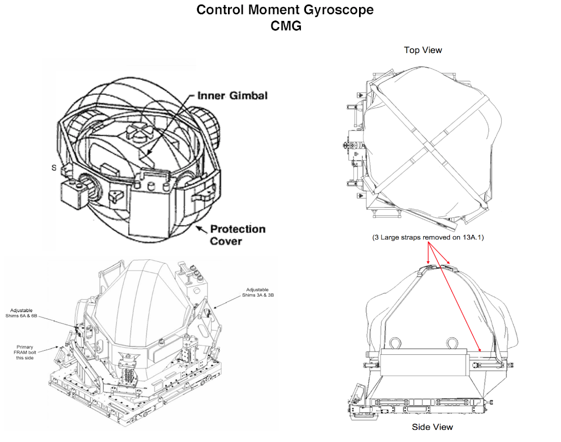
In the diagram, the gimbal axis is perpendicular to the rotor’s angular-momentum vector. Turning the gimbal changes the direction of the rotor momentum; the required rate of change produces a reaction torque on the spacecraft in the opposite direction. The torque direction is perpendicular to both the gimbal axis and the rotor momentum. The sketch is conceptual, not a wiring or mechanical installation drawing.
A calculation: large torque from a modest steering rate
Take a hypothetical CMG with H = 10 N·m·s and a perpendicular gimbal rate of Ω = 0.10 rad/s (about 5.7 degrees per second). The magnitude of its ideal steering torque is
τ = HΩ = 10 × 0.10 = 1.0 N·m.
That is an illustrative calculation, not the specification of a particular commercial unit. Halve the gimbal rate and the torque halves. Tilt the gimbal axis to make an angle of 30 degrees with the stored momentum and, for the same rate, the torque falls to 0.5 N·m. Align the axes and the cross product vanishes: that gimbal motion cannot change the momentum direction at all.
For scale, a NASA technical paper on the ISS describes four double-gimbal CMGs, each storing about 4,760 N·m·s of angular momentum and capable of an output torque of approximately 258 N·m. Their flywheels rotate at about 6,600 rpm. Dividing the quoted torque by the momentum gives an indicative transverse steering rate of 258/4760 ≈ 0.054 rad/s, or 3.1 degrees per second. This back-of-the-envelope rate is not a complete operational steering law: gimbal geometry, limits and spacecraft dynamics all matter.
Compare the two mechanisms carefully. A reaction wheel creates torque by changing spin magnitude: τ ≈ -I dω/dt. A CMG creates torque mainly by changing spin direction: τ ≈ -Ω × H. The minus signs express the spacecraft’s reaction, in a simplified body-fixed description. Both obey the same conservation law; the engineering choice is how to use it.
The mathematical trap: when four powerful gyros cannot turn you
One CMG cannot command an arbitrary three-dimensional torque. Real spacecraft therefore use several, with their gimbal axes arranged in different directions. A controller converts the desired body torque into a set of gimbal rates. Locally, that conversion has the form
τ = -A(δ) δ̇,
where δ represents the gimbal angles, δ̇ their rates, and the columns of the steering matrix A describe the torque direction produced by each gimbal. This is the point where a seemingly simple mechanical trick becomes a sophisticated control problem.
At some combinations of gimbal angles, the available torque directions become linearly dependent. The matrix loses rank for a direction that the controller needs. This is a singularity: the gyros may all be spinning normally, yet the requested torque cannot be produced by any finite choice of gimbal rates at that instant. More motor power does not fix a missing direction in the geometry.
Engineers address this with redundant gyros, careful mounting arrangements, trajectory planning and steering laws that avoid or pass through troublesome configurations. A widely studied approach uses a pseudoinverse of the steering matrix, with additional motion in its null space to rearrange the gimbals without changing the commanded torque at first order. But avoiding every singularity under every command is not generally guaranteed. The classic 1990 steering-law study by Bedrossian and colleagues and later experimental and numerical work on singularity avoidance show why the control software is as essential as the flywheel hardware.
What this makes possible—and what it cannot do
CMGs are useful when rapid, repeatable reorientation matters: scanning telescopes, agile Earth-observation satellites and large inhabited platforms. The ISS uses CMGs for continuous attitude control without routinely firing thrusters for each small correction. A NASA study of spacecraft momentum and power control examines how internal flywheels and CMGs can work together, including how they reduce propellant use.
Smaller spacecraft are beginning to benefit too. ESA’s 9 September 2026 report describes a compact 4.2 kg CMG developed with industry support and flight-tested on a commercial constellation. Its faster manoeuvres are encouraging, but the meaningful engineering comparison also includes pointing stability, power, mass, cost, lifetime and vibration—not manoeuvre time alone.
There are hard limits. A CMG cannot change a spacecraft’s centre-of-mass orbit by internal motion. External torques from gravity gradients, solar radiation pressure and residual atmosphere can gradually load the attitude-control system with unwanted momentum. Eventually the vehicle may need to unload that momentum using an external torque, such as magnetic torquers in suitable low-Earth orbits or thrusters. The ISS has used thrusters for momentum management as well. Fuel-free attitude manoeuvres do not imply a permanently propellant-free spacecraft.
Hardware is another constraint. Bearings, gimbal motors, structural flexibility and vibrations can degrade precision or cause failure. NASA’s ISS lessons-learned report documents early CMG failures and subsequent reliability improvements. ESA research on variable-speed CMGs highlights coupling to flexible spacecraft structures: making a large platform turn faster can excite the very vibrations that ruin accurate pointing.
Shape: experiment with the direction of momentum
A simple numerical experiment captures the heart of the idea. Fix the momentum magnitude at H = 10 N·m·s and the gimbal rate at Ω = 0.10 rad/s. Calculate τ = HΩ sin(α) for α = 0, 30, 60, 90 degrees. The corresponding ideal torque magnitudes are 0, 0.50, 0.87, 1.00 N·m. Draw the gimbal axis, momentum vector and their cross product at each angle. You will see the torque vanish at alignment even though the wheel never slows down.
For a tangible demonstration, hold a small, safely enclosed spinning gyroscope or bicycle-wheel model by its axle while seated on a freely swivelling stool, and gently change the axle’s direction. Keep fingers away from spokes and do not use a heavy or high-speed wheel. The unexpected reaction is easier to feel than to describe. The experiment illustrates angular-momentum exchange, but it does not reproduce a satellite’s free-floating dynamics or its full steering algorithm.
The next question is a design challenge: could a small spacecraft choose its camera targets and the order in which it visits them to avoid CMG singularities, save electrical power and reduce the need for momentum dumping? That is a richer problem than “point here next.” It turns a physics trick into a joint optimisation of geometry, scheduling, control and mission purpose.
Sources and further exploration
Primary technical references: Gurrisi et al., Space Station Control Moment Gyroscope Lessons Learned (2010); Bedrossian et al., steering laws for redundant single-gimbal CMGs (1990); Roithmayr et al., dynamics and control using flywheels and CMGs (NASA, 2003); Takada et al., singularity-avoidance steering (2010). Engineering context: ESA’s compact CMG flight report (2026) and ESA’s variable-speed CMG study.
Explore a different kind of passive motion control on Alkemata: how a tuned mass damper calms a skyscraper. Both designs use the motion of an internal mass, but one deliberately redirects angular momentum while the other absorbs structural oscillations.
Author
What did this make you think?
Choose a reaction or write a comment. Comments are reviewed before publication.