
A rocket engine has to contain gases hot enough to ruin the metal that surrounds them. The nozzle throat is especially unforgiving: the exhaust accelerates through its narrowest passage, and heat is transferred intensely into the wall. Simply choosing a stronger alloy does not solve the problem. The engine must keep its wall within a survivable temperature range while producing thrust for minutes, not milliseconds.
One of the most elegant solutions is to make the fuel do a second job before it burns. Route it through narrow passages behind the hot chamber wall, let it absorb heat, and only then send it to the injector. The same fluid becomes both coolant and propellant. This is regenerative cooling, a mature rocket-engine technique whose cleverness lies in the arrangement of energy flows rather than in a miraculous material.
It is not merely a historical curiosity. In an October 2025 description of Ariane 6’s Vulcain 2.1 nozzle, the European Space Agency reports more than a thousand small channels carrying hydrogen through the nozzle’s thin metallic wall. The gas can reach extreme temperatures; the metal survives because it does not have to reach the gas temperature.
Explore: the apparent impossibility of a hot rocket chamber
Imagine holding a thin copper cup near a flame. Copper conducts heat very well, which seems like a disadvantage: energy rapidly spreads into the metal. Yet in a rocket chamber that conductivity can be precisely what is needed. If the outer side of the wall is continuously cooled, heat crosses the metal instead of accumulating in it. A good conductor can sustain a large heat flow with a comparatively small temperature difference across a thin section.
The crucial distinction is between gas temperature, heat flux, and wall temperature. A very hot gas does not instantaneously make every surface equally hot. Heat has to pass through a gas-side boundary layer, the metal liner and a coolant-side boundary layer. Each stage offers thermal resistance. The wall reaches whatever temperature balances incoming and outgoing heat, provided the cooling system can maintain that balance.
NASA’s 1972 design-criteria monograph on fluid-cooled rocket combustion chambers treats regenerative cooling as a central engineering solution, but it also describes the practical enemies: non-uniform flow, pressure loss, cracks, leaks, thermal fatigue and difficult start-up transients. Cooling is a system problem, not a coating applied at the end of a design.
Understand: a heat exchanger wrapped around a rocket
In one common arrangement, a pump drives cold fuel into a manifold near the nozzle’s downstream end. The fuel travels through many parallel channels along the nozzle and chamber, often towards the injector. Hot combustion products flow inside the chamber and out of the nozzle; coolant travels on the other side of a thin metallic liner. The two streams are kept separate until the fuel reaches the injector. Other engines use different channel routings, multiple passes or additional cooling methods.
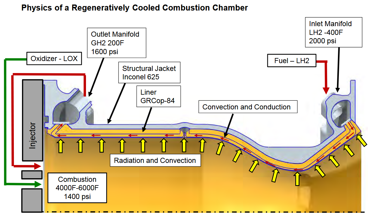
Read the drawing as a schematic, not an exact section of a particular engine. Heat crosses the wall from the hot gas into the coolant; the coolant carries that energy away as its enthalpy rises. The hot gas continues towards the nozzle exit. The warmed fuel is then used in the engine rather than dumped into a separate radiator. That is why the scheme is called regenerative.
Nothing here requires the fuel to remain a liquid throughout the channels. In a cryogenic hydrogen system, for example, its temperature and physical properties change considerably along the path, and the pressure may keep it in a dense supercritical state. The engineering question is whether its changing properties still allow adequate heat removal and stable flow.
Two small equations reveal the trick
The first is an energy balance. If the coolant absorbs a heat rate Q̇ and flows at mass rate ṁ, its specific enthalpy increase is approximately Δh = Q̇/ṁ. Suppose a simplified cooling circuit receives 1 MW of heat while 10 kg of coolant pass each second. The increase is 100,000 J/kg, or 100 kJ/kg. This is a deliberately illustrative calculation, not a prediction for a specific engine. Converting that enthalpy into a temperature change requires the coolant’s actual thermodynamic properties and pressure.
The second equation explains why a thin conductive wall is useful. For steady, one-dimensional conduction through a flat liner of thickness t and conductivity k, the temperature drop across the metal is approximately ΔTmetal = q″ t/k, where q″ is heat flux in W/m². Take an illustrative heat flux of 5 MW/m², a 0.5 mm wall and a conductivity of 300 W/(m K). The calculated drop through the metal alone is about 8.3 K.
That small number is easy to misread. It does not mean the wall sits 8.3 degrees above the coolant, nor that the engine is safe. There are additional temperature differences between hot gas and wall and between wall and coolant; geometry, coatings, local heat transfer and changing material properties matter. The calculation only isolates the metal’s conduction resistance. The broader lesson is that a thin, conductive liner can transmit intense heat to a flowing coolant without requiring an enormous temperature difference across the metal itself.
In a simplified resistance picture, q″ ≈ (Tg,eff - Tc)/(1/hg + t/k + 1/hc). Here hg and hc represent gas- and coolant-side heat-transfer coefficients, and Tg,eff is an effective driving temperature for the hot-gas boundary layer. This flat-wall model is only a guide to the competing resistances; a real rocket requires coupled fluid, thermal and structural analysis. NASA’s 1993 study of heat transfer in regeneratively cooled chambers addresses precisely that coupling.
The most difficult place is also where geometry can help
At the nozzle throat, heat transfer from the gas is often particularly severe. Designers can respond by tailoring the passages locally: changing their width, depth, number or distribution to increase coolant-side heat transfer where it is needed most. But faster flow and narrow channels also consume pumping pressure, increase sensitivity to tolerances and can create uneven flow between neighbouring passages.
There is a revealing example in a 1997 NASA comparison by Mary Wadel. In the analytical study of liquid-hydrogen cooling channels, manufacturable high-aspect-ratio designs reduced calculated hot-gas-side wall temperature by as much as 20% relative to a baseline, with some designs requiring pressure-drop increases as low as 2%. Those are results for the investigated geometries and assumptions, not a universal performance improvement. The interesting result is that where channels are reshaped can matter more than reshaping them everywhere: the study found no additional wall-temperature benefit from extending the high-aspect-ratio geometry along the entire chamber rather than concentrating it near the throat, while pressure loss increased.
This is an engineering form of selective attention. Instead of maximising cooling indiscriminately, the designer places heat-transfer capability where the wall is most threatened, while preserving the pressure budget needed by the rest of the engine.
Why the solution is not free
Regenerative cooling saves the mass and complexity of a separate cooling loop in many designs, but it does not abolish costs. The pump must overcome channel pressure loss. The wall must simultaneously withstand gas pressure, coolant pressure, thermal gradients and vibration. A joint that is easy to machine may be hard to inspect; a very thin liner may conduct heat beautifully but have little fatigue margin. Repeated heating and cooling can produce cracks, especially near highly stressed regions. Flow maldistribution can create a hot spot even when the total coolant flow appears adequate.
The start and shutdown sequences matter too. If hot gas arrives before sufficient coolant circulation, or if the coolant flow collapses while the chamber remains hot, a steady-state design calculation offers little comfort. NASA’s 1972 monograph specifically treats transients, thermal fatigue and leakage as central reliability problems. With some hydrocarbon fuels, unwanted chemical decomposition and deposits add another constraint; hydrogen and methane bring different material and fluid-property questions.
Regenerative cooling also does not automatically increase the total energy released by combustion. Heat transferred from the flame to the fuel is heat already present in the engine’s energy budget. Routing it through the propellant can reduce unwanted losses and support particular engine cycles, but the final effect on performance depends on the entire system. The elegant arrangement is not a perpetual-motion trick.
Shape: design the heat flow before designing the metal
A useful paper experiment needs no rocket hardware. Divide a hypothetical chamber into five axial sections, from injector to nozzle exit. Assign each a different heat load, with a peak near the throat, and imagine the same total coolant flow passing through all five. In a spreadsheet, accumulate the coolant’s enthalpy gain section by section using Δhi = Q̇i/ṁ. Plot the accumulated energy beside the local wall heat load. The plots immediately show that the coolant warms as it moves and that the hardest wall location is not necessarily the point where the coolant is warmest.
Next introduce a simplified cooling-channel design choice. Give each section a notional cooling effectiveness and pressure-loss penalty, then ask which sections deserve more of the available pressure budget. The exercise will not size a real engine; it makes the coupled trade-off visible. To progress beyond it would require validated fluid properties, spatial heat-transfer predictions, material limits, structural analysis, manufacturing tolerances and controlled testing.
The broader question reaches beyond rockets. When a component creates heat that threatens its survival, can the working fluid be routed to collect that heat before performing its main task? The answer sometimes turns waste heat into a useful part of the process. The cleverness is in making the same flow solve two problems, while remaining honest about the pressure, fatigue and reliability costs of asking it to do so.
Sources and further exploration
Primary technical references: NASA, Liquid Rocket Engine Fluid-Cooled Combustion Chambers (1972); Wadel, Comparison of High Aspect Ratio Cooling Channel Designs (1997); and NASA, Heat Transfer in Rocket Engine Combustion Chambers and Regeneratively Cooled Nozzles (1993). For a modern European example, see ESA’s October 2025 account of the Ariane 6 Vulcain 2.1 nozzle.
Related on Alkemata: how a heat pipe moves energy without a mechanical pump and how a lattice’s geometry changes its mechanical response.
